ASRock P4i45GL User Manual - Page 13
ASRock P4i45GL Manual
 |
View all ASRock P4i45GL manuals
Add to My Manuals
Save this manual to your list of manuals |
Page 13 highlights
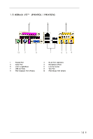
2.5 Installation of Memory Modules (DIMM) P4i45GL / P4i45GV motherboard provides two 184-pin DDR (Double Data Rate) DIMM slots. Please make sure to disconnect power supply before adding or removing DIMMs or the system components. Step 1. Step 2. Step 3. Unlock a DIMM slot by pressing the retaining clips outward. Align a DIMM on the slot such that the notch on the DIMM matches the break on the slot. Firmly insert the DIMM into the slot until the retaining clip snap back in place and the DIMM is properly seated. 2.6 Expansion Slots (PCI and AMR Slots) There are 2 PCI slots and 1 AMR slot on P4i45GL / P4i45GV motherboard. PCI slots: PCI slots are used to install expansion cards that have the 32-bit PCI interface. AMR slot: AMR slot is used to insert an ASRock MR card (optional) with v.92 Modem functionality. Installing an expansion card Step 1. Step 2. Step 3. Step 4. Step 5. Step 6. Before installing the expansion card, read the documentation of the expansion card and make necessary hardware settings for the card. Remove the system unit cover (if your motherboard is already installed in a chassis). Remove the bracket facing the slot that you intend to use. Keep the screws for later use. Align the card connector with the slot and press firmly until the card is completely seated on the slot. Fasten the card to the chassis with screws. Replace the system cover. 13
-
 1
1 -
2
-
3
-
4
-
5
-
6
-
7
-
 8
8 -
 9
9 -
 10
10 -
 11
11 -
 12
12 -
 13
13 -
 14
14 -
 15
15 -
 16
16 -
 17
17 -
 18
18 -
19
-
20
-
21
-
22
-
23
-
24
-
25
-
26
-
27
-
28
-
29
 |
 |
