ASRock P4i45GV R3.0 User Manual - Page 9
ASRock P4i45GV R3.0 Manual
 |
View all ASRock P4i45GV R3.0 manuals
Add to My Manuals
Save this manual to your list of manuals |
Page 9 highlights
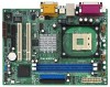
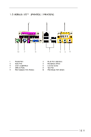
1.4 Motherboard Layout (P4i45GV) 1 2 3 4 17.8cm (7.0 in) 5 6 PS/2 Mouse 1 PS2_USB_PWR1 PARALLEL PORT Keyboard mPGA478B VGA LAN (optional) USB 2.0 Ports 28 USB 2.0 Ports DDR1 (64/72 bit, 184-pin module) DDR2 (64/72 bit, 184-pin module) 24.4cm (9.6 in) 7 8 9 10 11 CPU_FAN1 27 GAME AUDIO1 AUDIO1 GAME Line out Line In in Line Mic Mic in In 26 25 24 23 22 21 20 Intel 845GV Chipset AUDIO1 5.1CH USB2.0 IDE1 IDE2 1 PCI LAN 0 1 2 3 JR1 JL1 PCI 1 AUDIO CODEC Super I/O PCI 2 CMOS Battery COM1 Intel ICH4 CHA_FAN1 19 2MB BIOS FLOPPY1 SPEAKER1 1 USB45 CLRCMOS0 1 1 IR1 PLED PWRBTN 1 HDLED AMR1 1 RST 18 17 16 15 14 13 12 1 3 5 7 9 11 13 15 17 19 21 23 25 27 CPU Fan Connector (CPU_FAN1) CPU Heatsink Retention Module 184-pin DDR DIMM Slots (DDR DIMM1- 2) Primary IDE Connector (IDE1, Blue) South Bridge Controller External Speaker Connector (SPEAKER1) Infrared Module Connector (IR1) Clear CMOS (CLRCMOS0, 2-pin jumper) Serial Port Connector (COM1) BIOS FWH Chip PCI Slots (PCI 1- 2) JR1 Jumper PCI LAN (Optional) Internal Audio Connector: CD1 (Black) 2 4 6 8 10 12 14 16 18 20 22 24 26 28 PS2_USB_PWR1 Jumper CPU Socket ATX Power Connector (ATXPWR1) Secondary IDE Connector (IDE2, Black) Chassis Fan Connector (CHA_FAN1) System Panel Connector (PANEL1) USB 2.0 Header (USB45, Blue) Floppy Connector (FLOPPY1) AMR Slot (AMR1) AUDIO CODEC JL1 Jumper Front Panel Audio Connector (AUDIO1) Internal Audio Connector: AUX1 (White) North Bridge Controller P4i45GV PANEL 1 ATXPWR1 PS/2 9
-
 1
1 -
2
-
3
-
 4
4 -
 5
5 -
 6
6 -
 7
7 -
 8
8 -
 9
9 -
 10
10 -
 11
11 -
 12
12 -
 13
13 -
 14
14 -
15
-
16
-
17
-
18
-
19
-
20
-
21
-
22
-
23
-
24
-
25
-
26
-
27
-
28
-
29
 |
 |
