ASRock P4i65PE Quick Installation Guide - Page 2
Motherboard L, Motherboard Layout, ayout - bios
 |
View all ASRock P4i65PE manuals
Add to My Manuals
Save this manual to your list of manuals |
Page 2 highlights
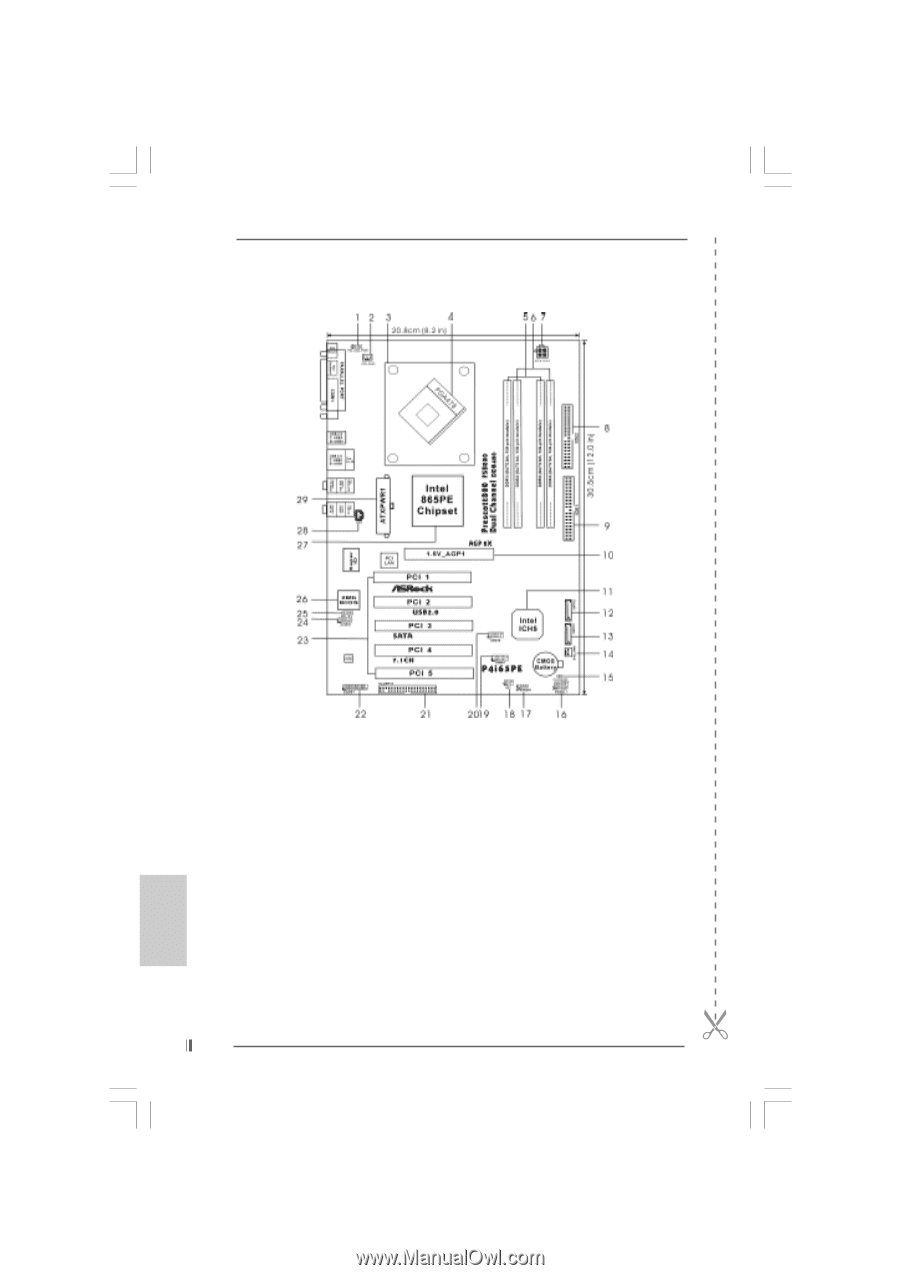
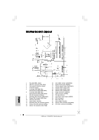
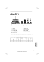
Motherboard Layout English 1 PS2_USB_PWR1 Jumper 2 CPU Fan Connector (CPU_FAN1) 3 CPU Heatsink Retention Module 4 P4-478 CPU Socket 5 2 x 184-pin DDR DIMM Slots (Dual Channel A: DDR1, DDR3; Blue) 6 2 x 184-pin DDR DIMM Slots (Dual Channel B: DDR2, DDR4; Black) 7 ATX 12V Connector (ATX12V1) 8 Secondary IDE Connector (IDE2, Black) 9 Primary IDE Connector (IDE1, Blue) 10 AGP Slot (1.5V_AGP1) 11 South Bridge Controller 12 Secondary Serial ATA Connector (SATA2) 13 Primary Serial ATA Connector (SATA1) 14 Chassis Fan Connector (CHA_FAN1) 15 Clear CMOS Jumper (CLRCMOS0) 16 System Panel Header (PANEL1) 17 Chassis Speaker Header (SPEAKER 1) 18 Infrared Module Header (IR1) 19 USB 2.0 Header (USB67, Blue) 20 USB 2.0 Header (USB45, Blue) 21 Floppy Connector (FLOPPY1) 22 Game Connector (GAME1) 23 PCI Slots (PCI1- 5) 24 Front Panel Audio Header (AUDIO1) 25 JR1 / JL1 Jumpers 26 BIOS FWH Chip 27 North Bridge Controller 28 Internal Audio Connector: CD1 (Black) 29 ATX Power Connector (ATXPWR1) 2 ASRock P4i65PE Motherboard
-
 1
1 -
 2
2 -
 3
3 -
 4
4 -
 5
5 -
 6
6 -
 7
7 -
 8
8 -
9
-
10
-
11
-
12
-
13
-
14
-
15
-
16
-
17
-
18
-
19
-
20
-
21
-
22
-
23
-
24
-
25
-
26
-
27
-
28
-
29
-
30
-
31
-
32
-
33
-
34
-
35
-
36
-
37
-
38
-
39
-
40
-
41
-
42
-
43
-
44
-
45
-
46
-
47
-
48
-
49
-
50
-
51
-
52
-
53
-
54
-
55
-
56
-
57
-
58
-
59
-
60
-
61
-
62
-
63
-
64
-
65
-
66
-
67
-
68
-
69
-
70
-
71
-
72
-
73
-
74
-
75
-
76
-
77
-
78
-
79
-
80
 |
 |