ASRock PE PRO User Manual - Page 11
Installation of CPU Fan and Heatsink, 5 Installation of Memory Modules DIMM
 |
View all ASRock PE PRO manuals
Add to My Manuals
Save this manual to your list of manuals |
Page 11 highlights
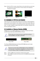
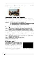
Step 4. When the CPU is in place, press it firmly on the socket while you push down the socket lever to secure the CPU. The lever clicks on the side tab to indicate that it is locked. Step 1 Step 2, 3 Step 4 2.4 Installation of CPU Fan and Heatsink Intel® Pentium®4 CPU requires larger heatsink and cooling fan. Thermal grease between the CPU and the heatsink is also needed to improve heat transfer. Make sure that the CPU and the heatsink are securely fastened and in good contact with each other. For proper installation, please kindly refer to the instruction manuals of the CPU fan and heatsink vendors. 2.5 Installation of Memory Modules (DIMM) SDRAM (Synchronous DRAM) DIMM (Dual In-line Memory Module) has 168 pins and DDR (Double Data Rate) SDRAM DIMM has 184 pins. Please make sure to disconnect power supply before adding or removing DIMMs or the system components. 168-pin RAM 184-pin RAM The 168-pin SDRAM DIMM (black) and 184-pin DDR DIMM (blue) can be easily distinguished by the fool-proof design. Please do not use both 168-pin SDRAM DIMM and 184-pin DDR DIMM at the same time. To optimize the compatibility, it is not recommended to use two different models of the DIMMs at the same time. Step 1. Step 2. Unlock a DIMM slot by pressing the retaining clips outward. Align a DIMM on the slot such that the notch on the DIMM matches the break on the slot. 11
-
 1
1 -
2
-
3
-
4
-
5
-
 6
6 -
 7
7 -
 8
8 -
 9
9 -
 10
10 -
 11
11 -
 12
12 -
 13
13 -
 14
14 -
 15
15 -
 16
16 -
17
-
18
-
19
-
20
-
21
-
22
-
23
-
24
-
25
-
26
 |
 |
