ASRock X299 Killer SLI/ac Quick Installation Guide - Page 5
I/O Panel
 |
View all ASRock X299 Killer SLI/ac manuals
Add to My Manuals
Save this manual to your list of manuals |
Page 5 highlights
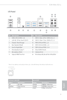
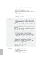
I/O Panel 1 X299 Killer SLI/ac 35 2 46 16 15 14 13 No. Description 1 USB 2.0 Port (USB_3_4) 2 LAN RJ-45 Port (Intel® I219V)* 3 Central / Bass (Orange) 4 Rear Speaker (Black) 5 Line In (Light Blue) 6 Front Speaker (Lime)** 7 Microphone (Pink) 8 Optical SPDIF Out Port 12 11 9 87 10 No. Description 9 USB 3.1 Type-A Port (USB31_TA_1) 10 USB 3.1 Type-C Port (USB31_TC_1) 11 USB 2.0 Ports (USB_1_2) 12 USB 3.0 Ports (USB3_1_2) 13 USB 3.0 Ports (USB3_3_4) 14 Clear CMOS Switch 15 Antenna Ports 16 PS/2 Mouse/Keyboard Port (PS2_KB1) * There are two LEDs on each LAN port. Please refer to the table below for the LAN port LED indications. ACT/LINK LED SPEED LED LAN Port Activity / Link LED Status Off Blinking On Description No Link Data Activity Link Speed LED Status Orange Orange Green Description 10Mbps connection 100Mbps connection 1Gbps connection 3 English
-
 1
1 -
 2
2 -
 3
3 -
 4
4 -
 5
5 -
 6
6 -
 7
7 -
 8
8 -
 9
9 -
 10
10 -
 11
11 -
12
-
13
-
14
-
15
-
16
-
17
-
18
-
19
-
20
-
21
-
22
-
23
-
24
-
25
-
26
-
27
-
28
-
29
-
30
-
31
-
32
-
33
-
34
-
35
-
36
-
37
-
38
-
39
-
40
-
41
-
42
-
43
-
44
-
45
-
46
-
47
-
48
-
49
-
50
-
51
-
52
-
53
-
54
-
55
-
56
-
57
-
58
-
59
-
60
-
61
-
62
-
63
-
64
-
65
-
66
-
67
-
68
-
69
-
70
-
71
-
72
-
73
-
74
-
75
-
76
-
77
-
78
-
79
-
80
-
81
-
82
-
83
-
84
-
85
-
86
-
87
-
88
-
89
-
90
-
91
-
92
-
93
-
94
-
95
-
96
-
97
-
98
-
99
-
100
-
101
-
102
-
103
-
104
-
105
-
106
-
107
-
108
-
109
-
110
-
111
-
112
-
113
-
114
-
115
-
116
-
117
-
118
-
119
-
120
-
121
-
122
-
123
-
124
-
125
-
126
-
127
-
128
-
129
-
130
-
131
-
132
-
133
-
134
-
135
-
136
-
137
-
138
-
139
-
140
-
141
-
142
-
143
-
144
-
145
-
146
-
147
-
148
-
149
-
150
-
151
-
152
-
153
-
154
-
155
-
156
-
157
-
158
-
159
-
160
-
161
-
162
-
163
-
164
-
165
-
166
-
167
-
168
-
169
-
170
-
171
-
172
-
173
-
174
-
175
-
176
-
177
-
178
-
179
-
180
-
181
-
182
-
183
-
184
-
185
-
186
-
187
-
188
-
189
-
190
-
191
-
192
-
193
-
194
-
195
-
196
-
197
-
198
 |
 |
