ASRock Z170 Extreme4 User Manual
ASRock Z170 Extreme4 Manual
 |
View all ASRock Z170 Extreme4 manuals
Add to My Manuals
Save this manual to your list of manuals |
ASRock Z170 Extreme4 manual content summary:
- ASRock Z170 Extreme4 | User Manual - Page 1
- ASRock Z170 Extreme4 | User Manual - Page 2
and should not be constructed as a commitment by ASRock. ASRock assumes no responsibility for any errors or omissions that may appear in this documentation. With CALIFORNIA, USA ONLY he Lithium battery adopted on this motherboard contains Perchlorate, a toxic substance controlled in Perchlorate Best - ASRock Z170 Extreme4 | User Manual - Page 3
he terms HDMI™ and HDMI High-Deinition Multimedia Interface, and the HDMI logo are trademarks or registered trademarks of HDMI Licensing LLC in the United States and other countries. Manufactured under license under U.S. Patent Nos: 5,956,674; 5,974,380; 6,487,535; 7,003,467 & other U.S. and - ASRock Z170 Extreme4 | User Manual - Page 4
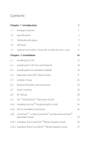
2 1.3 Motherboard Layout 7 1.4 I/O Panel 9 1.5 ASRock Front USB 3.1 Panel (for Z170 Extreme4+ only) 11 Chapter 2 Installation 14 2.1 Installing the CPU 15 2.2 Installing the CPU Fan and Heatsink 18 2.3 Installing Memory Modules (DIMM) 19 2.4 Expansion Slots (PCI Express Slots) 21 - ASRock Z170 Extreme4 | User Manual - Page 5
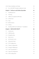
38 2.11 M.2_SSD (NGFF) Module Installation Guide 39 Chapter 3 Software and Utilities Operation 42 3.1 Installing Drivers 42 3.2 A-Tuning 43 3.3 ASRock Live Update & APP Shop 47 3.3.1 UI Overview 47 3.3.2 Apps 48 3.3.3 BIOS & Drivers 51 3.3.4 Setting 52 3.4 Enabling USB Ports - ASRock Z170 Extreme4 | User Manual - Page 6
4.4.7 USB Coniguration 81 4.4.8 Trusted Computing 82 4.5 Tools 83 4.6 Hardware Health Event Monitoring Screen 87 4.7 Security Screen 89 4.8 Boot Screen 90 4.9 Exit Screen 93 - ASRock Z170 Extreme4 | User Manual - Page 7
cards and CPU support list on ASRock's website as well. ASRock website http://www.asrock.com. 1.1 Package Contents • ASRock Z170 Extreme4+ / Z170 Extreme4 Motherboard (ATX Form Factor) • ASRock Z170 Extreme4+ / Z170 Extreme4 Quick Installation Guide • ASRock Z170 Extreme4+ / Z170 Extreme4 Support CD - ASRock Z170 Extreme4 | User Manual - Page 8
Intel® Turbo Boost 2.0 Technology • Supports Intel® K-Series unlocked CPUs • Supports ASRock BCLK Full-range Overclocking • Supports ASRock Hyper BCLK Engine Chipset • Intel® Z170 Memory • Dual Channel DDR4 Memory Technology • 4 x DDR4 DIMM Slots • Supports DDR4 3200+(OC)*/2933(OC)/2800(OC - ASRock Z170 Extreme4 | User Manual - Page 9
Z170 Extreme4+ / Z170 Extreme4 Audio • Supports Intel® HD Graphics Built-in Visuals : Intel® Quick Sync Video with AVC, MVC (S3D) and MPEG-2 Full HW Encode1, Intel® InTruTM 3D, Intel® Clear Video HD Technology, Intel® InsiderTM, Intel® HD Graphics 510/530 • Pixel Shader 5.0, DirectX 12 • Max. - ASRock Z170 Extreme4 | User Manual - Page 10
Ports (Intel® Z170) (Supports ESD Protection (ASRock Full Spike Protection)) • 1 x RJ-45 LAN Port with LED (ACT/LINK LED and SPEED LED) • 1 x Clear CMOS Switch • HD Audio Jacks: Rear Speaker / Central / Bass / Line in / Front Speaker / Microphone ASRock Front USB 3.1 Panel (for Z170 Extreme4+ only - ASRock Z170 Extreme4 | User Manual - Page 11
Switch with LED • 1 x Reset Switch with LED BIOS Feature • 2 x 128Mb AMI UEFI Legal BIOS with multilingual GUI support (1 x Main BIOS and 1 x Backup BIOS) • Supports Secure Backup UEFI Technology • ACPI 1.1 Compliant wake up events • SMBIOS 2.3.1 Support • CPU, GT_CPU, DRAM, VPPM, PCH 1.0V, VCCIO - ASRock Z170 Extreme4 | User Manual - Page 12
into the ISO ile is required. Please refer to page 53 for more detailed instructions. * For the updated Windows® 10 driver, please visit ASRock's website for details: http://www.asrock.com • FCC, CE, WHQL • ErP/EuP Ready (ErP/EuP ready power supply is required) * For detailed product information - ASRock Z170 Extreme4 | User Manual - Page 13
1.3 Motherboard Layout Z170 Extreme4+ / Z170 Extreme4 PS2 Center: FRONT Bottom: MIC IN LAN CHA_FAN1 PCIE1 PCI Express 3.0 PCIE2 CMOS Battery Front USB 3.0 USB3_7_8 1 USB_3_4 1 Intel Z170 CLRMOS1 1 Power Reset BIOS_B1 128Mb BIOS BIOS_B_LED BIOS_A1 128Mb BIOS BIOS_A_LED 1 BIOS_SEL1 - ASRock Z170 Extreme4 | User Manual - Page 14
) 15 System Panel Header (PANEL1) 16 SATA and SATA Express Connectors (SATA3_5_4, SATA_EXP2) 17 Reset Switch (RSTBTN1) 18 Power Switch (PWRBTN1) 19 Clear CMOS Jumper (CLRMOS1) 20 USB 2.0 Header (USB_3_4) 21 USB 2.0 Header (USB_1_2) 22 hunderbolt AIC Connector (TB1) 23 TPM Header (TPMS1) 24 COM Port - ASRock Z170 Extreme4 | User Manual - Page 15
1.4 I/O Panel 1 2 Z170 Extreme4+ / Z170 Extreme4 46 3 57 17 16 15 14 No. Description 1 PS/2 Mouse/Keyboard Port 2 DVI-D Port 3 LAN RJ-45 Port* 4 Central / Bass (Orange) 5 Rear USB 3.0 Ports (USB3_34) 14 DisplayPort 1.2 15 HDMI Port 16 Clear CMOS Switch 17 USB 3.0 Ports (USB3_12) English 9 - ASRock Z170 Extreme4 | User Manual - Page 16
indications. ACT/LINK LED SPEED LED LAN Port Activity / Link LED Status Of Blinking On Description No Link Data Activity Link Speed LED Status Of Orange Green Description 10Mbps connection 100Mbps connection 1Gbps connection ** If you use a 2-channel speaker, please connect the speaker's plug - ASRock Z170 Extreme4 | User Manual - Page 17
Z170 Extreme4+ / Z170 Extreme4 1.5 ASRock Front USB 3.1 Panel (for Z170 Extreme4+ only) Speciications Dimension • 75mm (W) x 42.8mm (H) x 148mm (L) Controller • ASMedia ASM1142 Controller Front Panel I/O • 1 x USB 3.1 Type-A Port (10 Gb/s) (Supports ESD Protection (ASRock Full Spike - ASRock Z170 Extreme4 | User Manual - Page 18
3.1 Panel Front USB 3.1 Panel ASRock Front USB 3.1 Panel Installation Guide Step 1 Prepare the bundled ASRock Front USB 3.1 Panel, SATA Express Cable, USB Power Cable and screws. Step 2 Connect one end of the SATA Express Cable to the SATA Express Connector on the ASRock Front USB 3.1 Panel. Step - ASRock Z170 Extreme4 | User Manual - Page 19
English Z170 Extreme4+ / Z170 Extreme4 Step 5 Screw ASRock Front USB 3.1 Panel to the drive bay with screws. SATA3_4_5 SATA3_A1_A2 SATA3_A3_A4 SATA_EXP0 SATA3_1_3 SATA3_0_2 Step 6 Connect the PSU's SATA Power Cable to the SATA Power Connector. Step 7 Connect the other end of the SATA Express - ASRock Z170 Extreme4 | User Manual - Page 20
Pre-installation Precautions Take note of the following precautions before you install motherboard components or change any motherboard settings. • Make sure to unplug the power cord before installing or removing the motherboard components. Failure to do so may cause physical injuries and damages to - ASRock Z170 Extreme4 | User Manual - Page 21
Z170 Extreme4+ / Z170 Extreme4 2.1 Installing the CPU 1. Before you insert the 1151-Pin CPU into the socket, please check if the PnP cap is on the socket, if the CPU surface is unclean, or if there are any bent pins in the socket. Do not force to insert the CPU into the socket if above situation is - ASRock Z170 Extreme4 | User Manual - Page 22
4 5 16 3 English - ASRock Z170 Extreme4 | User Manual - Page 23
Z170 Extreme4+ / Z170 Extreme4 Please save and replace the cover if the processor is removed. he cover must be placed if you wish to return the motherboard for ater service. 17 English - ASRock Z170 Extreme4 | User Manual - Page 24
2.2 Installing the CPU Fan and Heatsink 1 2 CPU_FAN English 18 - ASRock Z170 Extreme4 | User Manual - Page 25
Z170 Extreme4+ / Z170 Extreme4 2.3 Installing Memory Modules (DIMM) his motherboard provides four 288-pin DDR4 (Double Data Rate 4) DIMM slots, and supports Dual Channel Memory Technology. 1. For dual channel coniguration, you always need to install identical (the same brand, speed, size and chip- - ASRock Z170 Extreme4 | User Manual - Page 26
1 2 3 20 English - ASRock Z170 Extreme4 | User Manual - Page 27
Z170 Extreme4+ / Z170 Extreme4 2.4 Expansion Slots (PCI Express Slots) here are 6 PCI Express slots on the motherboard. Before installing an expansion card, please make sure that the power supply is switched of or the power cord is unplugged. Please read the documentation - ASRock Z170 Extreme4 | User Manual - Page 28
on CLRMOS1 for 5 seconds. However, please do not clear the CMOS right ater you update the BIOS. If you need to clear the CMOS when you just inish updating the BIOS, you must boot up the system irst, and then shut it down before you do the clear-CMOS action. Please be noted that the password, date - ASRock Z170 Extreme4 | User Manual - Page 29
Z170 Extreme4+ / Z170 Extreme4 BIOS Selection Jumper (BIOS_SEL1) (see p.7, No. 12) Default Backup BIOS (Main BIOS) his motherboard has two BIOS onboard, a main BIOS (BIOS_A) and a backup BIOS (BIOS_B), which enhances protection for the safety and stability of your system. Normally, the system - ASRock Z170 Extreme4 | User Manual - Page 30
place jumper caps over these headers and connectors. Placing jumper caps over the headers and connectors will cause permanent damage to the motherboard. System Panel Header (9-pin PANEL1) (see p.7, No. 15) PLED+ PLEDPWRBTN# GND 1 GND RESET# GND HDLEDHDLED+ Connect the power switch, reset switch - ASRock Z170 Extreme4 | User Manual - Page 31
Z170 Extreme4+ / Z170 Extreme4 Power LED and Speaker p.7, No. 16) SATA3_1 SATA3_0 SATA3_3 SATA3_2 hese six SATA3 connectors support SATA data cables for internal storage devices with up to 6.0 Gb/s here are two headers on this motherboard. Each USB 2.0 header can support two ports. 25 English - ASRock Z170 Extreme4 | User Manual - Page 32
I/O panel, there is one header on this motherboard. Each USB 3.0 header can support two ports. Front Panel Audio Header (9-pin HD_AUDIO1 supports Jack Sensing, but the panel wire on the chassis must support HDA to function correctly. Please follow the instructions in our manual and chassis manual - ASRock Z170 Extreme4 | User Manual - Page 33
Z170 Extreme4+ / Z170 Extreme4 CPU Fan Connectors (4-pin CPU_FAN1) (see p.7, No. 3) (4-pin CPU_FAN2) (see p.7, No. 2) FAN_SPEED FAN_VOLTAGE_CONTROL GND FAN_SPEED_CONTROL his motherboard provides a 4-Pin CPU fan (Quiet Fan) connector. If you plan to connect a 3-Pin CPU fan, please connect it to - ASRock Z170 Extreme4 | User Manual - Page 34
SMB_CLK_MAIN GN D +3VS B LAD0 +3V LAD3 PCIRST # FRAM E PCICLK his connector supports Trusted Platform Module (TPM) system, 1 which can securely store keys, digital certiicates, passwords, and data. A TPM system also helps enhance network security, protects digital identities, and ensures - ASRock Z170 Extreme4 | User Manual - Page 35
Z170 Extreme4+ / Z170 Extreme4 2.7 Smart Switches he motherboard has three smart switches: Power Switch, Reset Switch and Clear CMOS Switch, allowing users to quickly turn on/of the system, reset the system or clear the CMOS values. Power Switch (PWRBTN) (see p.7, No. 18) Power Switch allows - ASRock Z170 Extreme4 | User Manual - Page 36
Debug Dr. Debug is used to provide code information, which makes troubleshooting even easier. Please see the diagrams below for reading the Dr. Debug codes. Code Description 00 Please check if the CPU is installed correctly and then clear CMOS. 0d Problem related to memory, VGA card or other - ASRock Z170 Extreme4 | User Manual - Page 37
Z170 Extreme4+ / Z170 Extreme4 b4 Problem related to USB devices. Please try removing all USB devices. b7 Problem related to memory. Please re-install the CPU and memory then clear CMOS. If the problem still exists, please install only one memory module or try using other memory modules. d6 - ASRock Z170 Extreme4 | User Manual - Page 38
Operation Guide his motherboard supports NVIDIA 2. Make sure that your graphics card driver supports NVIDIA® SLITM technology. Download the drivers from the NVIDIA® website: www.nvidia PCIE2 slot and the other graphics card to PCIE4 slot. Make sure that the cards are properly seated on the slots. - ASRock Z170 Extreme4 | User Manual - Page 39
Z170 Extreme4+ / Z170 Extreme4 Step 3 Align and insert the ASRock SLI_ Bridge_2S Card to the goldingers on each graphics card. Make sure the ASRock SLI_ Bridge_2S Card is irmly in place. SLI_Bridge_2S Card ASRock SLI_Bridge_2S Card Step 4 Connect a VGA cable or a DVI cable to the monitor connector - ASRock Z170 Extreme4 | User Manual - Page 40
Installation and Setup Install the graphics card drivers to your system. Ater that, you can enable the Multi-Graphics Processing Unit (GPU) in the NVIDIA® nView system tray utility. Please follow the below - ASRock Z170 Extreme4 | User Manual - Page 41
Z170 Extreme4+ / Z170 Extreme4 2.10 CrossFireXTM , 3-Way CrossFireXTM and Quad CrossFireXTM Operation Guide his motherboard supports CrossFireXTM, 3-way CrossFireXTM and Quad CrossFireXTM that allows you to install up to three identical PCI Express x16 graphics cards. 1. You should only use - ASRock Z170 Extreme4 | User Manual - Page 42
Step 3 Connect a VGA cable or a DVI cable to the monitor connector or the DVI connector of the graphics card that is inserted to PCIE2 slot. 36 English - ASRock Z170 Extreme4 | User Manual - Page 43
Z170 Extreme4+ / Z170 Extreme4 2.10.2 Installing Three CrossFireXTM-Ready Graphics Cards Step 1 Insert one graphics card into PCIE2 slot, another graphics card to PCIE4 slot, and the other graphics card to PCIE6 slot. Make sure that the cards are properly seated on the slots. CrossFire Bridge - ASRock Z170 Extreme4 | User Manual - Page 44
optional download. We recommend using this utility to uninstall any previously installed Catalyst drivers prior to installation. Please check AMD's website for AMD driver updates. Step 3 Install the required drivers and CATALYST Control Center then restart your computer. Please check AMD's website - ASRock Z170 Extreme4 | User Manual - Page 45
Z170 Extreme4+ / Z170 Extreme4 2.11 M.2_SSD (NGFF) Module Installation Guide The M.2, also known as the Next Generation Form Factor (NGFF), is a small size and versatile card edge connector that aims to replace mPCIe and mSATA. The Ultra M.2 Socket (M2_1) supports M.2 PCI Express module up to Gen3 - ASRock Z170 Extreme4 | User Manual - Page 46
4 Peel of the yellow protective ilm on the nut to be used. Hand tighten the standof into the desired nut location on the motherboard. Step 5 Align and gently insert the M.2 (NGFF) SSD module into the M.2 slot. Please be aware that the M.2 (NGFF) SSD module only its in one orientation. English 40 - ASRock Z170 Extreme4 | User Manual - Page 47
Z170 Extreme4+ / Z170 Extreme4 E D NUT2 NUT1 Step 6 Tighten the screw with a screwdriver to secure the module into place. Please do not overtighten the screw as this might damage the module. M.2_SSD (NGFF) Module Support List Vendor ADATA ADATA ADATA Crucial Crucial Intel Kingston Kingston - ASRock Z170 Extreme4 | User Manual - Page 48
those required drivers. herefore, the drivers you install can work properly. Utilities Menu he Utilities Menu shows the application sotware that the motherboard supports. Click on a speciic item then follow the installation wizard to install it. To improve Windows 7 compatibility, please download - ASRock Z170 Extreme4 | User Manual - Page 49
Z170 Extreme4+ / Z170 Extreme4 3.2 A-Tuning A-Tuning is ASRock's multi purpose sotware suite with a new interface, more new features and improved utilities. 3.2.1 Installing A-Tuning When you install the all-in-one driver to your system from ASRock's support CD, A-Tuning will be auto-installed as - ASRock Z170 Extreme4 | User Manual - Page 50
OC Tweaker Conigurations for overclocking the system. System Info View information about the system. *he System Browser tab may not appear for certain models. 44 English - ASRock Z170 Extreme4 | User Manual - Page 51
Z170 Extreme4+ / Z170 Extreme4 FAN-Tastic Tuning Conigure up to ive diferent fan speeds using the graph. he fans will automatically shit to the next speed level when the assigned temperature is met. Tech Service Contact Tech Service if you have problems with your computer. Please leave your contact - ASRock Z170 Extreme4 | User Manual - Page 52
Settings Conigure ASRock A-Tuning. Click to select "Auto run at Windows Startup" if you want A-Tuning to be launched when you start up the Windows operating system. 46 English - ASRock Z170 Extreme4 | User Manual - Page 53
Extreme4+ / Z170 Extreme4 3.3 ASRock Live Update & APP Shop he ASRock Live Update & APP Shop is an online store for purchasing and downloading sotware applications for your ASRock computer. You can quickly and easily install various apps and support utilities, such as USB Key, XFast LAN, XFast RAM - ASRock Z170 Extreme4 | User Manual - Page 54
on the right. Please scroll up and down to see more apps listed. You can check the price of the app and whether you have already intalled it or not. - he red icon displays the price or "Free" if the app is free of charge. - he green "Installed" icon means the app - ASRock Z170 Extreme4 | User Manual - Page 55
Z170 Extreme4+ / Z170 Extreme4 Step 3 If you want to install the app, click on the red icon to start downloading. Step 4 When installation completes, you can ind the green " - ASRock Z170 Extreme4 | User Manual - Page 56
Upgrading an App You can only upgrade the apps you have already installed. When there is an available new version for your app, you will ind the mark of "New Version" appears below the installed app icon. Step 1 Click on the app icon to see more details. Step 2 Click on the yellow icon to start - ASRock Z170 Extreme4 | User Manual - Page 57
Z170 Extreme4+ / Z170 Extreme4 3.3.3 BIOS & Drivers Installing BIOS or Drivers When the "BIOS & Drivers" tab is selected, you will see a list of recommended or critical updates for the BIOS or drivers. Please update them all soon. Step 1 Please check the item information before update. Click on - ASRock Z170 Extreme4 | User Manual - Page 58
3.3.4 Setting In the "Setting" page, you can change the language, select the server location, and determine if you want to automatically run the ASRock Live Update & APP Shop on Windows startup. 52 English - ASRock Z170 Extreme4 | User Manual - Page 59
Z170 Extreme4+ / Z170 Extreme4 3.4 Enabling USB Ports for Windows® 7 Installation Intel® Braswell and Skylake has removed their support drivers, users may ind it diicult to install Windows 7 operating system because the USB ports on their motherboard and follow the instructions below to create - ASRock Z170 Extreme4 | User Manual - Page 60
it. Step 3 Select the "Win7 Folder" from Step1 by clicking the red circle as shown as the picture below. Step 4 Select the "USB Driver Folder" by clicking the red circle as shown as the picture below. If you are using ASRock's Support CD for the USB 3.0 driver, please select your CD-ROM. 54 English - ASRock Z170 Extreme4 | User Manual - Page 61
Z170 Extreme4+ / Z170 Extreme4 Step 5 Select where to save the ISO ile by pressing the red circle as shown as the picture below. Step 6 If you want to burn Braswell or Skylake with the new burned CD. Or please use the patched ISO image to make an OS USB drive to install the OS. 55 English - ASRock Z170 Extreme4 | User Manual - Page 62
the screen has a menu bar with the following selections: Main For setting system time/date information OC Tweaker For overclocking conigurations Advanced For advanced system conigurations Tool Useful tools H/W Monitor Displays current hardware status Boot For coniguring boot settings and - ASRock Z170 Extreme4 | User Manual - Page 63
Z170 Extreme4+ / Z170 Extreme4 4.1.2 Navigation Keys Use < > key or < > key to choose among the selections on the menu bar, and use < > key or < > key to move the cursor up - ASRock Z170 Extreme4 | User Manual - Page 64
4.2 Main Screen When you enter the UEFI SETUP UTILITY, the Main screen will appear and display the system overview. Z170 Extreme4+: Z170 Extreme4: Favorite Display your collection of BIOS items. Press F5 to add/remove your favorite items. 58 English - ASRock Z170 Extreme4 | User Manual - Page 65
appears only when your CPU supports this function. his option appears only when you adopt K-Series CPU. Load Optimized CPU OC Setting You can use this option to load optimized CPU overclocking setting. Please note that overclocking may cause damage to your CPU and motherboard. It should be done - ASRock Z170 Extreme4 | User Manual - Page 66
interference for passing EMI tests. Disable to achieve higher clock speeds when overclocking. CPU Amplitude Conigure the CPU Amplitude. Boot Performance Mode Select the performance state that the BIOS will set before OS handof. Reliability Stress Restrictor Disable or Enable Reliability - ASRock Z170 Extreme4 | User Manual - Page 67
Z170 Extreme4+ / Z170 Extreme4 FCLK Frequency Conigure the FCLK Frequency. Intel SpeedStep Slice Current Limit Conigure the current limit of the GT slice. A lower limit can protect the CPU and save power, while a higher limit may improve performance. GT Slice Frequency Conigure the frequency of - ASRock Z170 Extreme4 | User Manual - Page 68
optimized settings. DRAM Frequency If [Auto] is selected, the motherboard will detect the memory module(s) inserted and assign the appropriate If the DRAM frequency is selected, the corresponding DRAM and BCLK frequency for overclocking will be set. Primary Timing CAS# Latency (tCL) he time between - ASRock Z170 Extreme4 | User Manual - Page 69
Z170 Extreme4+ / Z170 Extreme4 Secondary Timing Write Recovery Time (tWR) he amount of delay that must elapse ater the completion of a valid write operation, before an active bank can - ASRock Z170 Extreme4 | User Manual - Page 70
tCKE Conigure the period of time the DDR4 initiates a minimum of one refresh command internally once it enters Self-Refresh mode. tRDRD_sg Conigure between module read to read delay. tRDRD_dg Conigure between module read to read delay. tRDRD_dr Conigure between module read to read delay. tRDRD_dd - ASRock Z170 Extreme4 | User Manual - Page 71
latency for channel B. IO-L (CH A) Conigure IO latency for channel A. IO-L (CH B) Conigure IO latency for channel B. Fourth Timing twRPRE Conigure twRPRE. Write_Early_ODT Conigure Write_Early_ODT. tAONPD Conigure tAONPD. tXP Conigure tXP. tXPDLL Conigure tXPDLL. Z170 Extreme4+ / Z170 Extreme4 65 - ASRock Z170 Extreme4 | User Manual - Page 72
Conigure tZQOPER. tMOD Conigure tMOD. ZQCS_period Conigure ZQCS_period. tZQCS Conigure tZQCS. Advanced Setting ODT WR (CH A) Conigure the memory on die termination resistors' WR for channel A. ODT WR (CH B) Conigure the memory on die termination resistors' WR for - ASRock Z170 Extreme4 | User Manual - Page 73
Z170 Extreme4+ / Z170 Extreme4 ODT PARK (CH A) Conigure the memory on die termination resistors' PARK for channel A. ODT PARK (CH B) Conigure the memory on die termination resistors' PARK for channel B. ODT NOM (CH A) Use this to change ODT (CH A) Auto/Manual settings. he default is [Auto]. ODT NOM - ASRock Z170 Extreme4 | User Manual - Page 74
Save User Default Type a proile name and press enter to save your settings as user default. Load User Default Load previously saved user defaults. 68 English - ASRock Z170 Extreme4 | User Manual - Page 75
Z170 Extreme4+ / Z170 Extreme4 4.4 Advanced Screen In this section, you may set the conigurations for the following items: CPU resolution will be set to 1920 x 1080 if the monitor supports Full HD resolution. If the monitor does not support Full HD resolution, then the resolution will be set to 1024 - ASRock Z170 Extreme4 | User Manual - Page 76
overall performance on threaded sotware is improved. Active Processor Cores Select the number of cores to enable in each processor package. CPU C States Support Enable CPU C States Support for power saving. It is recommended to keep C3, C6 and C7 all enabled for better power saving. Enhanced Halt - ASRock Z170 Extreme4 | User Manual - Page 77
Z170 Extreme4+ / Z170 Extreme4 No-Execute Memory Protection Processors with No-Execution Memory Protection can function as multiple virtual systems. Hardware Prefetcher Automatically prefetch data and code for the processor. Enable for better performance. Adjacent Cache Line Prefetch Automatically - ASRock Z170 Extreme4 | User Manual - Page 78
helps your virtual machine monitor better utilize hardware by improving application compatibility and reliability, and providing additional levels of manageability, security, speed for PCIE6. PCIE ASPM Support his option enables/disables the ASPM support for all CPU downstream devices. 72 English - ASRock Z170 Extreme4 | User Manual - Page 79
Z170 Extreme4+ / Z170 Extreme4 PCH PCIE ASPM Support his option enables/disables the ASPM support for all PCH PCIE devices. DMI ASPM Support his option enables/disables the control of ASPM on CPU side of the DMI Link. PCH DMI ASPM Support his option enables/disables the ASPM support for all PCH DMI - ASRock Z170 Extreme4 | User Manual - Page 80
Good Night LED By enabling Good Night LED, the Power/HDD LEDs will be switched of when the system is on. It will also automatically switch of the Power and Keyboard LEDs when the system enters into Standby/Hibernation mode. Onboard Debug Port LED Enable/disable the onboard Dr. Debug LED. 74 English - ASRock Z170 Extreme4 | User Manual - Page 81
Storage Coniguration Z170 Extreme4+ / Z170 Extreme4 SATA Controller(s) Enable/disable the SATA controllers. SATA Mode Selection AHCI: Supports new features that improve performance. RAID: Combine multiple disk drives into a logical unit. AHCI (Advanced Host Controller Interface) supports NCQ and - ASRock Z170 Extreme4 | User Manual - Page 82
M2_1/SATA3_0_1, SATA_EXP0 Switch Auto: M2_1/SATA3_0_1, SATA_EXP0 auto switch. Force_SATA: Switch to SATA3_0_1, SATA_EXP0. Force_M2_1: Switch to M2_1. 76 English - ASRock Z170 Extreme4 | User Manual - Page 83
4.4.4 Intel® Thunderbolt™ 2 Z170 Extreme4+ / Z170 Extreme4 Intel(R) Thunderbolt Technonogy Enable/Disable the Intel(R) hunderbolt function. English 77 - ASRock Z170 Extreme4 | User Manual - Page 84
4.4.5 Super IO Coniguration Serial Port Enable or disable the Serial port. Serial Port Address Select the address of the Serial port. PS2 Y-Cable Enable the PS2 Y-Cable or set this option to Auto. 78 English - ASRock Z170 Extreme4 | User Manual - Page 85
ACPI Coniguration Z170 Extreme4+ / Z170 Extreme4 Suspend to RAM Select disable for ACPI suspend type S1. It is recommended to select auto for ACPI S3 power saving. ACPI HEPT Table Enable the High Precision Event Timer for better performance. PS/2 Keyboard Power On Allow the system to be waked up - ASRock Z170 Extreme4 | User Manual - Page 86
USB Mouse Power On Allow the system to be waked up by an USB mouse. 80 English - ASRock Z170 Extreme4 | User Manual - Page 87
4.4.7 USB Coniguration Z170 Extreme4+ / Z170 Extreme4 Legacy USB Support Enable or disable Legacy OS Support for USB 2.0 devices. If you encounter USB compatibility issues it is recommended to disable legacy USB support. Select UEFI Setup Only to support USB devices under the UEFI setup and - ASRock Z170 Extreme4 | User Manual - Page 88
4.4.8 Trusted Computing Security Device Support Enable or disable BIOS support for security device. 82 English - ASRock Z170 Extreme4 | User Manual - Page 89
ASRock Tech Service if you are having trouble with your PC. Please setup network coniguration before using UEFI Tech Service. Easy RAID Installer Easy RAID Installer helps you to copy the RAID driver from the support CD to your USB storage device. Ater copying the drivers please change the SATA - ASRock Z170 Extreme4 | User Manual - Page 90
from our support CD, Easy Driver Installer is a handy tool in the UEFI that installs the LAN driver to your system via an USB storage device, then downloads and installs the other required drivers automatically. Boot Manager Boot Manager is speciically designed for the dual OS platform/multi-OS - ASRock Z170 Extreme4 | User Manual - Page 91
Z170 Extreme4+ / Z170 Extreme4 Dehumidiier Period Conigure the period of time until the computer powers on and enables Dehumidiier ater entering S4/S5 state. Dehumidiier Duration Conigure the duration of the dehumidifying process before it returns to S4/S5 state. Dehumidiier CPU Fan Setting Conigure - ASRock Z170 Extreme4 | User Manual - Page 92
Network Coniguration Use this to conigure internet connection settings for Internet Flash. Internet Setting Enable or disable sound efects in the setup utility. UEFI Download Server Select a server to download the UEFI irmware. 86 English - ASRock Z170 Extreme4 | User Manual - Page 93
Z170 Extreme4+ / Z170 Extreme4 4.6 Hardware Health Event Monitoring Screen his section allows you to monitor the status of the hardware on your system, including the parameters of the CPU temperature, motherboard temperature, fan speed and voltage. Fan-Tastic Tuning Select a fan mode for CPU Fans - ASRock Z170 Extreme4 | User Manual - Page 94
Fan 3 Setting Select a fan mode for Chassis Fan 3, or choose Customize to set 5 CPU temperatures and assign a respective fan speed for each temperature. Chassis Fan 3 Temp Source Select a Protection is enabled, the system automatically shuts down when the motherboard is overheated. 88 English - ASRock Z170 Extreme4 | User Manual - Page 95
Z170 Extreme4+ / Z170 Extreme4 4.7 Security Screen In this section you may set or change the supervisor/user password for the system. You may also clear . Secure Boot Use this item to enable or disable support for Windows 8.1 Secure Boot. Intel(R) Platform Trust Technology Enable/disable Intel PTT - ASRock Z170 Extreme4 | User Manual - Page 96
must support UEFI GOP if you are using an external graphics card. Please notice that Ultra Fast mode will boot so fast that the only way to enter this UEFI Setup Utility is to Clear CMOS or run the Restart to UEFI utility in Windows. Boot From Onboard LAN Allow the system to be waked - ASRock Z170 Extreme4 | User Manual - Page 97
Z170 Extreme4+ / Z170 Extreme4 Full Screen Logo Enable to display the boot logo or disable to show normal POST messages. AddOn ROM Display Enable AddOn ROM Display to see - ASRock Z170 Extreme4 | User Manual - Page 98
Module) CSM Enable to launch the Compatibility Support Module. Please do not disable unless you're running a WHCK test. If you are using Windows 8.1 64-bit and all of your devices support UEFI, you may also disable CSM for faster boot speed. Launch PXE OpROM Policy Select UEFI only to run those - ASRock Z170 Extreme4 | User Manual - Page 99
4.9 Exit Screen Z170 Extreme4+ / Z170 Extreme4 Save Changes and Exit When you select this option the following message, "Save coniguration changes and exit setup?" will pop out. Select [OK] to save - ASRock Z170 Extreme4 | User Manual - Page 100
or want to know more about ASRock, you're welcome to visit ASRock's website at http://www.asrock.com; or you may contact your dealer for further information. For technical questions, please submit a support request form at http://www.asrock.com/support/tsd.asp ASRock Incorporation 2F., No.37, Sec
-
 1
1 -
 2
2 -
 3
3 -
 4
4 -
 5
5 -
 6
6 -
 7
7 -
8
-
9
-
10
-
11
-
12
-
13
-
14
-
15
-
16
-
17
-
18
-
19
-
20
-
21
-
22
-
23
-
24
-
25
-
26
-
27
-
28
-
29
-
30
-
31
-
32
-
33
-
34
-
35
-
36
-
37
-
38
-
39
-
40
-
41
-
42
-
43
-
44
-
45
-
46
-
47
-
48
-
49
-
50
-
51
-
52
-
53
-
54
-
55
-
56
-
57
-
58
-
59
-
60
-
61
-
62
-
63
-
64
-
65
-
66
-
67
-
68
-
69
-
70
-
71
-
72
-
73
-
74
-
75
-
76
-
77
-
78
-
79
-
80
-
81
-
82
-
83
-
84
-
85
-
86
-
87
-
88
-
89
-
90
-
91
-
92
-
93
-
94
-
95
-
96
-
97
-
98
-
99
-
100
 |
 |
