ASRock Z270 Killer SLI/ac Quick Installation Guide - Page 28
Only one Tunderbolt AIC
 |
View all ASRock Z270 Killer SLI/ac manuals
Add to My Manuals
Save this manual to your list of manuals |
Page 28 highlights
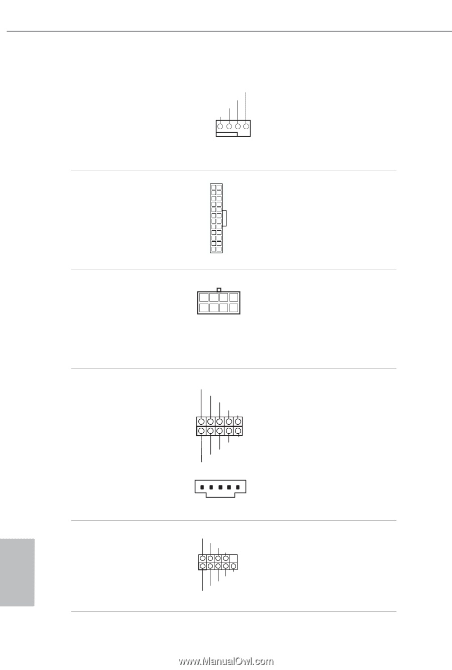
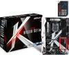
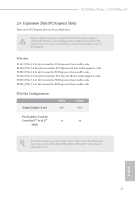
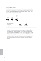
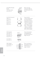
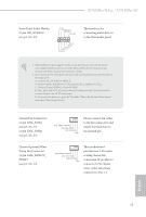
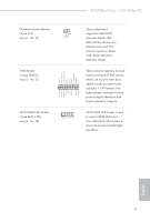
English CPU Fan Connector (4-pin CPU_FAN1) (see p.1, No. 4) ATX Power Connector (24-pin ATXPWR1) (see p.1, No. 5) ATX 12V Power Connector (8-pin ATX12V1) (see p.1, No. 1) Thunderbolt AIC Connectors (10-pin TB1) (see p.1, No. 24) (5-pin TB2) (see p.1, No. 20) Serial Port Header (9-pin COM1) (see p.1, No. 22) 26 FAN_SPEED_CONTROL CPU_FAN_SPEED FAN_VOLTAGE GND 1 2 34 This motherboard provides a 4-Pin CPU fan (Quiet Fan) connector. If you plan to connect a 3-Pin CPU fan, please connect it to Pin 1-3. 12 24 1 13 This motherboard provides a 24-pin ATX power connector. To use a 20-pin ATX power supply, please plug it along Pin 1 and Pin 13. 8 5 This motherboard pro- vides an 8-pin ATX 12V power connector. To use a 4 1 4-pin ATX power supply, please plug it along Pin 1 and Pin 5. DUMMY I2C_DATA I2C_CLOCK IRQ GND 1 GND SLP_S4# SLP_S3# PLUG_EVENT FRC_PWR Please connect a Thunderbolt™ add-in card (AIC) to the Thunderbolt AIC connector via the GPIO cable. * Please install the Thunderbolt™ AIC card to PCIE4 (default slot). * Only one Thunderbolt AIC Card is supported on this motherboard. RRXD1 DDTR#1 DDSR#1 CCTS#1 1 RRI#1 RRTS#1 GND TTXD1 DDCD#1 This COM1 header supports a serial port module.
-
 1
1 -
2
-
3
-
4
-
5
-
6
-
7
-
8
-
9
-
10
-
11
-
12
-
13
-
14
-
15
-
16
-
17
-
18
-
19
-
20
-
21
-
22
-
 23
23 -
 24
24 -
 25
25 -
 26
26 -
 27
27 -
 28
28 -
 29
29 -
 30
30 -
 31
31 -
 32
32 -
 33
33 -
34
-
35
-
36
-
37
-
38
-
39
-
40
-
41
-
42
-
43
-
44
-
45
-
46
-
47
-
48
-
49
-
50
-
51
-
52
-
53
-
54
-
55
-
56
-
57
-
58
-
59
-
60
-
61
-
62
-
63
-
64
-
65
-
66
-
67
-
68
-
69
-
70
-
71
-
72
-
73
-
74
-
75
-
76
-
77
-
78
-
79
-
80
-
81
-
82
-
83
-
84
-
85
-
86
-
87
-
88
-
89
-
90
-
91
-
92
-
93
-
94
-
95
-
96
-
97
-
98
-
99
-
100
-
101
-
102
-
103
-
104
-
105
-
106
-
107
-
108
-
109
-
110
-
111
-
112
-
113
-
114
-
115
-
116
-
117
-
118
-
119
-
120
-
121
-
122
-
123
-
124
-
125
-
126
-
127
-
128
-
129
-
130
-
131
-
132
-
133
-
134
-
135
-
136
-
137
-
138
-
139
-
140
-
141
-
142
-
143
-
144
-
145
-
146
-
147
-
148
-
149
-
150
-
151
-
152
-
153
-
154
-
155
-
156
-
157
-
158
-
159
-
160
-
161
-
162
-
163
-
164
-
165
-
166
-
167
-
168
-
169
-
170
-
171
-
172
-
173
-
174
-
175
 |
 |