ASRock Z270 Killer SLI/ac User Manual - Page 31
pin CHA_FAN3/W - tpm
 |
View all ASRock Z270 Killer SLI/ac manuals
Add to My Manuals
Save this manual to your list of manuals |
Page 31 highlights
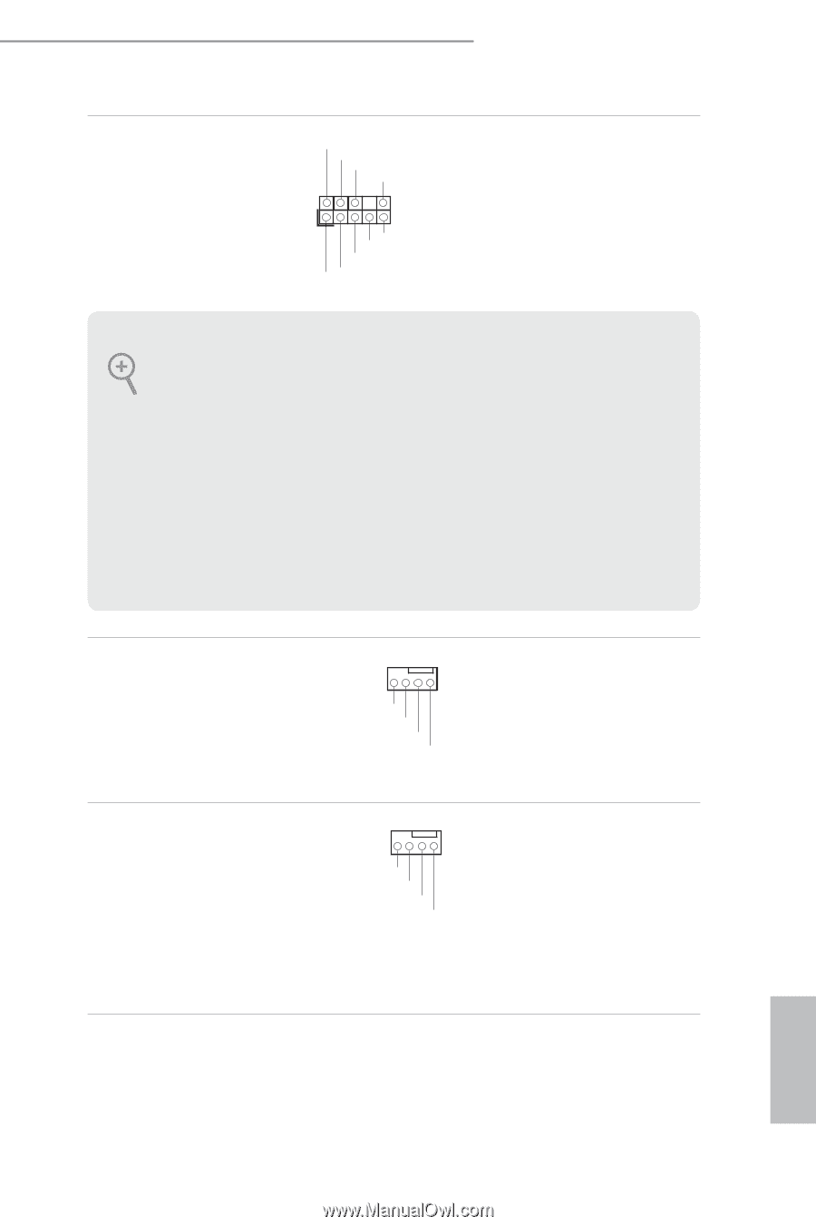
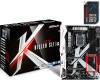
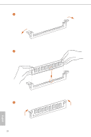
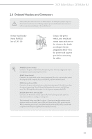
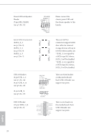
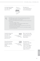
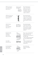
Z270 Killer SLI/ac / Z270 Killer SLI Front Panel Audio Header (9-pin HD_AUDIO1) (see p.7, No. 23) GND PRESENCE# MIC_RET OUT_RET 1 OUT2_L J_SENSE OUT2_R MIC2_R MIC2_L This header is for connecting audio devices to the front audio panel. 1. High Definition Audio supports Jack Sensing, but the panel wire on the chassis must support HDA to function correctly. Please follow the instructions in our manual and chassis manual to install your system. 2. If you use an AC'97 audio panel, please install it to the front panel audio header by the steps below: A. Connect Mic_IN (MIC) to MIC2_L. B. Connect Audio_R (RIN) to OUT2_R and Audio_L (LIN) to OUT2_L. C. Connect Ground (GND) to Ground (GND). D. MIC_RET and OUT_RET are for the HD audio panel only. You don't need to connect them for the AC'97 audio panel. E. To activate the front mic, go to the "FrontMic" Tab in the Realtek Control panel and adjust "Recording Volume". Chassis Fan Connectors (4-pin CHA_FAN1) (see p.7, No. 13) (4-pin CHA_FAN2) (see p.7, No. 25) FAN_SPEED_CONTROL CHA_FAN_SPEED FAN_VOLTAGE GND Please connect fan cables to the fan connectors and match the black wire to the ground pin. Chassis Optional/Water Pump Fan Connector (4-pin CHA_FAN3/W_ PUMP) (see p.7, No. 12) FAN_SPEED_CONTROL CHA_FAN_SPEED FAN_VOLTAGE GND This motherboard provides two 4-Pin water cooling chassis fan connectors. If you plan to connect a 3-Pin chassis water cooler fan, please connect it to Pin 1-3. English 25
-
 1
1 -
2
-
3
-
4
-
5
-
6
-
7
-
8
-
9
-
10
-
11
-
12
-
13
-
14
-
15
-
16
-
17
-
18
-
19
-
20
-
21
-
22
-
23
-
24
-
25
-
 26
26 -
 27
27 -
 28
28 -
 29
29 -
 30
30 -
 31
31 -
 32
32 -
 33
33 -
 34
34 -
 35
35 -
 36
36 -
37
-
38
-
39
-
40
-
41
-
42
-
43
-
44
-
45
-
46
-
47
-
48
-
49
-
50
-
51
-
52
-
53
-
54
-
55
-
56
-
57
-
58
-
59
-
60
-
61
-
62
-
63
-
64
-
65
-
66
-
67
-
68
-
69
-
70
-
71
-
72
-
73
-
74
-
75
-
76
-
77
-
78
-
79
-
80
-
81
-
82
-
83
-
84
-
85
-
86
-
87
-
88
-
89
-
90
-
91
-
92
-
93
 |
 |