ASRock Z68 Extreme7 Gen3 User Manual - Page 47
one PS2 Mouse/Keyboard port
 |
View all ASRock Z68 Extreme7 Gen3 manuals
Add to My Manuals
Save this manual to your list of manuals |
Page 47 highlights
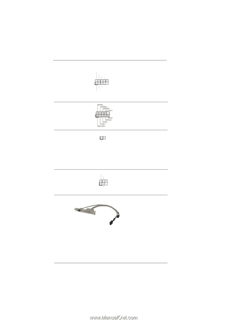
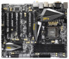
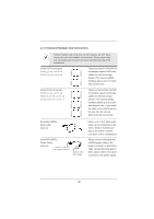
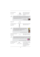
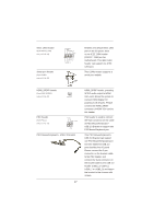
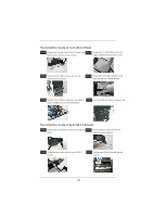
IEEE 1394 Header (9-pin FRONT_1394) (see p.13 No. 32) Serial port Header (9-pin COM1) (see p.13 No. 35) RXTPAM_0 GND RXTPBM_0 +12V GND 1 +12V RXTPBP_0 GND RXTPAP_0 Besides one default IEEE 1394 port on the I/O panel, there is one IEEE 1394 header (FRONT_1394) on this motherboard. This IEEE 1394 header can support one IEEE 1394 port. This COM1 header supports a serial port module. HDMI_SPDIF Header (2-pin HDMI_SPDIF1) (see p.13 No. 37) 1 GND SPDIFOUT PS2 Header (5-pin PS2_1) (see p.13 No. 33) DATA CLK PWR(+5VSB) 1 GND PS/2 Mouse/Keyboard + USB 2.0 Bracket 47 HDMI_SPDIF header, providing SPDIF audio output to HDMI VGA card, allows the system to connect HDMI Digital TV/ projector/LCD devices. Please connect the HDMI_SPDIF connector of HDMI VGA card to this header. PS2 header is used to connect the 5-pin connector on the cable of PS/2 Mouse/Keyboard + USB 2.0 Bracket to support one PS2 Mouse/Keyboard port. This PS/2 Mouse/Keyboard + USB 2.0 Bracket can support one PS2 Mouse/Keyboard port and two additional USB 2.0 ports besides the I/O panel. Please connect the 5-pin connector on the bracket cable to the PS2 header, and connect the 9-pin connector on the bracket cable to the USB 2.0 header (USB2_3, USB4_5, USB6_7 or USB8_9) and fasten the bracket to the chassis with screws.
-
 1
1 -
2
-
3
-
4
-
5
-
6
-
7
-
8
-
9
-
10
-
11
-
12
-
13
-
14
-
15
-
16
-
17
-
18
-
19
-
20
-
21
-
22
-
23
-
24
-
25
-
26
-
27
-
28
-
29
-
30
-
31
-
32
-
33
-
34
-
35
-
36
-
37
-
38
-
39
-
40
-
41
-
 42
42 -
 43
43 -
 44
44 -
 45
45 -
 46
46 -
 47
47 -
 48
48 -
 49
49 -
 50
50 -
 51
51 -
 52
52 -
53
-
54
-
55
-
56
-
57
-
58
-
59
-
60
-
61
-
62
-
63
-
64
-
65
-
66
-
67
-
68
-
69
-
70
-
71
-
72
-
73
-
74
-
75
-
76
-
77
-
78
-
79
-
80
-
81
-
82
-
83
-
84
-
85
-
86
-
87
-
88
 |
 |