ASRock Z690 Phantom Gaming 4 User Manual - Page 30
orientation; otherwise, the cable
 |
View all ASRock Z690 Phantom Gaming 4 manuals
Add to My Manuals
Save this manual to your list of manuals |
Page 30 highlights
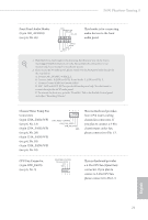
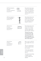
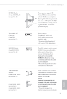
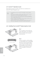
Z690 Phantom Gaming 4 SPI TPM Header (13-pin SPI_TPM_J1) (see p.6, No. 21) SPI_DQ3 SPI_PWR Dummy CLK SPI_MOSI RST# TPM_PIRQ 1 SPI_TPM_CS# GND RSMRST# SPI_MISO SPI_CS0 SPI_DQ2 This connector supports SPI Trusted Platform Module (TPM) system, which can securely store keys, digital certificates, passwords, and data. A TPM system also helps enhance network security, protects digital identities, and ensures platform integrity. 1 Thunderbolt AIC Connector (5-pin TB1) (see p.6, No. 27) RGB LED Header (4-pin RGB_LED1) (see p.6, No. 24) Addressable LED Headers (3-pin ADDR_LED1) (see p.6, No. 25) (3-pin ADDR_LED2) (see p.6, No. 8) (3-pin ADDR_LED3) (see p.6, No. 7) 1 +12V G R B 1 GND DO_ADDR VOUT GND DO_ADDR VOUT 1 Please connect a Thunderbolt™ add-in card (AIC) to this connector via the GPIO cable. *Please install the Thunderbolt™ AIC card to PCIE3 (default slot). This RGB header is used to connect RGB LED extension cable which allow users to choose from various LED lighting effects. Caution: Never install the RGB LED cable in the wrong orientation; otherwise, the cable may be damaged. *Please refer to page 52 for further instructions on this header. These headers are used to connect Addressable LED extension cables which allow users to choose from various LED lighting effects. Caution: Never install the Addressable LED cable in the wrong orientation; otherwise, the cable may be damaged. *Please refer to page 53 for further instructions on this header. 23 English
-
 1
1 -
2
-
3
-
4
-
5
-
6
-
7
-
8
-
9
-
10
-
11
-
12
-
13
-
14
-
15
-
16
-
17
-
18
-
19
-
20
-
21
-
22
-
23
-
24
-
 25
25 -
 26
26 -
 27
27 -
 28
28 -
 29
29 -
 30
30 -
 31
31 -
 32
32 -
 33
33 -
 34
34 -
 35
35 -
36
-
37
-
38
-
39
-
40
-
41
-
42
-
43
-
44
-
45
-
46
-
47
-
48
-
49
-
50
-
51
-
52
-
53
-
54
-
55
-
56
-
57
-
58
-
59
-
60
-
61
-
62
-
63
-
64
-
65
-
66
-
67
-
68
-
69
-
70
-
71
-
72
-
73
-
74
-
75
-
76
-
77
-
78
-
79
-
80
-
81
-
82
-
83
-
84
-
85
-
86
-
87
-
88
-
89
-
90
-
91
-
92
-
93
-
94
-
95
-
96
-
97
-
98
-
99
-
100
-
101
-
102
-
103
-
104
-
105
-
106
-
107
-
108
-
109
 |
 |
