ASRock Z97 Extreme6 User Manual - Page 30
Please connect the HDD Saver
 |
View all ASRock Z97 Extreme6 manuals
Add to My Manuals
Save this manual to your list of manuals |
Page 30 highlights
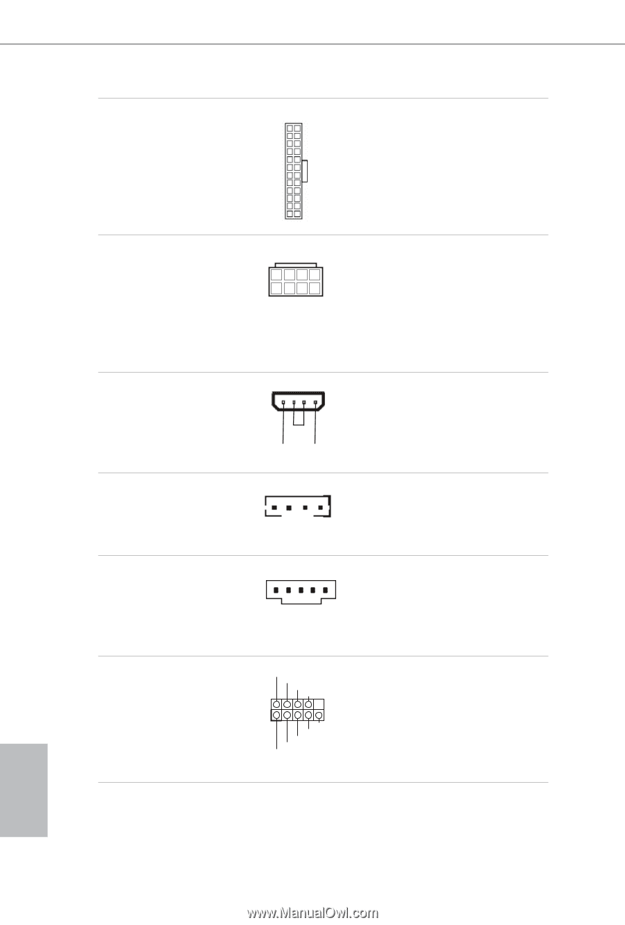
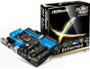
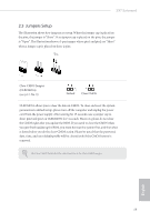
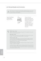
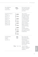
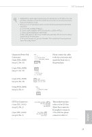
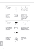
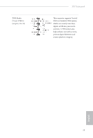
ATX Power Connector (24-pin ATXPWR1) (see p.12, No. 7) ATX 12V Power Connector (8-pin ATX12V1) (see p.12, No. 1) PCIe Power Connector (4-pin PCIE_PWR1) (see p.12, No. 30) HDD Saver Connector (4-pin SATA_PWR_1) (see p.12, No. 22) Thunderbolt AIC Connector (5-pin TB1) (see p.12, No. 28) Serial Port Header (9-pin COM1) (see p.12, No. 31) 12 24 1 13 8 5 4 1 GND +12V DETECT 1 This motherboard provides a 24-pin ATX power connector. To use a 20-pin ATX power supply, please plug it along Pin 1 and Pin 13. This motherboard provides an 8-pin ATX 12V power connector. To use a 4-pin ATX power supply, please plug it along Pin 1 and Pin 5. Please connect a 4 pin molex power cable to this connector when more than three graphics cards are installed. Please connect the HDD Saver Cable to this connector to manage the power state of HDD. Please connect a Thunderbolt™ add-in card (AIC) to this connector via the GPIO cable. RRXD1 DDTR#1 DDSR#1 CCTS#1 1 RRI#1 RRTS#1 GND TTXD1 DDCD#1 This COM1 header supports a serial port module. English 24
-
 1
1 -
2
-
3
-
4
-
5
-
6
-
7
-
8
-
9
-
10
-
11
-
12
-
13
-
14
-
15
-
16
-
17
-
18
-
19
-
20
-
21
-
22
-
23
-
24
-
 25
25 -
 26
26 -
 27
27 -
 28
28 -
 29
29 -
 30
30 -
 31
31 -
 32
32 -
 33
33 -
 34
34 -
 35
35 -
36
-
37
-
38
-
39
-
40
-
41
-
42
-
43
-
44
-
45
-
46
-
47
-
48
-
49
-
50
-
51
-
52
-
53
-
54
-
55
-
56
-
57
-
58
-
59
-
60
-
61
-
62
-
63
-
64
-
65
-
66
-
67
-
68
-
69
-
70
-
71
-
72
-
73
-
74
-
75
-
76
-
77
-
78
-
79
-
80
-
81
-
82
-
83
-
84
-
85
-
86
-
87
-
88
-
89
-
90
-
91
-
92
-
93
-
94
-
95
-
96
-
97
-
98
-
99
-
100
-
101
-
102
-
103
-
104
-
105
-
106
-
107
-
108
-
109
-
110
-
111
-
112
-
113
-
114
-
115
-
116
-
117
-
118
-
119
-
120
-
121
-
122
-
123
-
124
-
125
-
126
-
127
-
128
-
129
 |
 |