Aastra OpenPhone 63 User guide OpenPhone 60 on the OpenCom 1000 - Page 6
Cleaning Your Telephone, Adjusting the Inclination, Wall Mounting, Labelling the Keys, The IP - manual
 |
View all Aastra OpenPhone 63 manuals
Add to My Manuals
Save this manual to your list of manuals |
Page 6 highlights
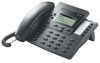
The Design of Your Telephone Cleaning Your Telephone Simply wipe your telephone with a slightly damp or anti-static cloth. Never use a dry cloth or a cleaning agent. it upside down and then replace it again (2). 1 Adjusting the Inclination 3 2 1 Pull out the feet (1) and turn them forwards or backwards (2) - two levels are possible. Then push the feet back in (3). Wall Mounting To mount your phone on the wall, please remove the feet by pulling them out sideways, then insert them into the recesses on the base of the telephone so that it later hangs flush with the wall. Use a screwdriver to lift the holding clip (1) for the handset from its slot, turn 8 Using Your Telephone 2 3 For wall mounting, two drill holes are required in the wall at the following distance apart: Telephone OpenPhone 61 OpenPhone 63 OpenPhone 65 Distance 155 mm 155 mm 184 mm The Design of Your Telephone In each hole, insert a wall plug and then screw in a 6mm screw so that the head of the screw protrudes approx 2.5 - 3mm from the wall. Mount the telephone on the screws. Labelling the Keys The keys assigned to the display are automatically or manually labelled during programming. The text then appears in the display. If keys have not been programmed, then no text is displayed. On the OpenPhone 61 and 63 there are five additional programmable keys without display support. To label the insert proceed as follows: The IP Version The IP version of the telephone also has a power socket and two RJ-45 sockets. Please insert the plug of the power supply cable in the corresponding socket of your telephone. Use the RJ45 socket labelled "LAN" to connect to your network and the RJ-45 socket labelled "PC" to connect to your PC. Press the bottom part of the cover (1) and push it slightly downwards (2). The upper part of the cover will then lift up and you can remove this and the labelling strip. To replace the cover, place it in the slot, then press it down before pushing it up until the holding clips click into place. Using Your Telephone 9
-
 1
1 -
 2
2 -
 3
3 -
 4
4 -
 5
5 -
 6
6 -
 7
7 -
 8
8 -
 9
9 -
 10
10 -
 11
11 -
 12
12 -
13
-
14
-
15
-
16
-
17
-
18
-
19
-
20
-
21
-
22
-
23
-
24
-
25
-
26
-
27
-
28
-
29
-
30
-
31
-
32
-
33
-
34
-
35
-
36
-
37
-
38
-
39
-
40
-
41
 |
 |
