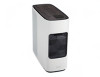
Acer ConceptD 700 User Manual
Acer ConceptD 700 Manual
 |
View all Acer ConceptD 700 manuals
Add to My Manuals
Save this manual to your list of manuals |
Acer ConceptD 700 manual content summary:
- Acer ConceptD 700 | User Manual - Page 1
ConceptD User Manual ConceptD 700 - Acer ConceptD 700 | User Manual - Page 2
are for reference only and may contain information or features that do not apply to your computer. Acer Group shall not be liable for technical or editorial errors or omissions contained in this manual. The terms HDMI and HDMI High-Definition Multimedia Interface, and the HDMI Logo are trademarks or - Acer ConceptD 700 | User Manual - Page 3
Table of Contents UPGRADING YOUR COMPUTER 1 Installation precautions 1 ESD precautions 1 Required tools 1 Pre-installation instructions.....2 Post-installation instructions ..2 System Upgrade 3 Removing the rear system cover 3 Installing the rear system cover 5 Removing the left side system - Acer ConceptD 700 | User Manual - Page 4
Upgrading your Computer In this section, you will find: • Instructions on how to replace a hardware component - Acer ConceptD 700 | User Manual - Page 5
that you read the following sections. These sections contain important ESD precautions along with pre-installation and post-installation instructions. ESD precautions Electrostatic discharge (ESD) can damage your processor, disk drives, expansion boards, and other components. Always observe the - Acer ConceptD 700 | User Manual - Page 6
may cause serious damage. Do not attempt the procedures described in the following sections unless you are a qualified service technician. Post-installation instructions Observe the following after installing a computer component: 1. See to it that the components are installed according to the - Acer ConceptD 700 | User Manual - Page 7
System Upgrade UPGRADING YOUR COMPUTER - 3 Removing the rear system cover 1. Before you proceed, make sure that you have turned off your computer and all peripherals connected to it. Read the Pre- installation instructions on page 2. 2. Release the Cable latch(1) and (2) 1 2 - Acer ConceptD 700 | User Manual - Page 8
4 - UPGRADING YOUR COMPUTER 3. Remove the four screws that secure the system cover to the computer. 4. Take off the rear system cover. 5. Set the cover aside for re-installation later. - Acer ConceptD 700 | User Manual - Page 9
UPGRADING YOUR COMPUTER - 5 Installing the rear system cover 1. Align the cover to the sides of the computer and slide the cover toward the front of the computer. 2. Insert the rear system cover 3. Secure the cover with four screws. - Acer ConceptD 700 | User Manual - Page 10
6 - UPGRADING YOUR COMPUTER 4. Install the Cable latch(1) and (2) 1 2 5. Observe the Post-installation instructions on page 2. - Acer ConceptD 700 | User Manual - Page 11
system cover 1. Before you proceed, make sure that you have turned off your computer and all peripherals connected to it. Read the Pre- installation instructions on page 2. 2. Remove the two screws that secure the system cover to the computer. 3. Slide the cover toward the back of the computer and - Acer ConceptD 700 | User Manual - Page 12
8 - UPGRADING YOUR COMPUTER Installing the left side system cover 1. Align the cover to the sides of the computer and slide the cover toward the front of the computer. 2. Secure the cover with two screws. 3. Observe the Post-installation instructions on page 2. - Acer ConceptD 700 | User Manual - Page 13
system cover 1. Before you proceed, make sure that you have turned off your computer and all peripherals connected to it. Read the Pre- installation instructions on page 2. 2. Remove the two screws that secure the system cover to the computer. 3. Slide the cover toward the back of the computer and - Acer ConceptD 700 | User Manual - Page 14
10 - UPGRADING YOUR COMPUTER Installing the right side system cover 1. Align the cover to the sides of the computer and slide the cover toward the front of the computer. 2. Secure the cover with two screws. 3. Observe the Post-installation instructions on page 2. - Acer ConceptD 700 | User Manual - Page 15
UPGRADING YOUR COMPUTER - 11 Hard drives The computer supports installation of one 3.5-inch SATA hard drives in the internal HDD cage. Removing the 3.5-inch hard drives 1. Perform Pre-installation instructions on page 2. 2. Disconnect the power and data cables from the hard drives. 3. Release the - Acer ConceptD 700 | User Manual - Page 16
12 - UPGRADING YOUR COMPUTER 5. Remove the HDD bracket from the chassis. 6. Remove the four screws that secure the hard drives to the bracket. 7. Remove the hard drives from the bracket. - Acer ConceptD 700 | User Manual - Page 17
UPGRADING YOUR COMPUTER - 13 Installing the 3.5-inch hard drives 1. Remove the new hard drive from their packaging. 2. Insert the new hard drive into the HDD bracket. 3. Secure the new hard drives with four screws. 4. Insert the HDD bracket into the chassis. - Acer ConceptD 700 | User Manual - Page 18
14 - UPGRADING YOUR COMPUTER 5. Secure the HDD bracket with three screws 6. Connect the power and data cables to the hard drives. 7. Use the cable clip to secure the cables. 8. Observe the Post-installation instructions on page 2 - Acer ConceptD 700 | User Manual - Page 19
Memory UPGRADING YOUR COMPUTER - 15 The computer has four DDR4 U-DIMM slots that support up to 64 GB maximum system memory. Memory configuration guidelines DIMM4 DIMM2 DIMM3 DIMM1 To ensure data integrity, use only Acer-approved DDR4 2400 MHz or DDR4 2666 MHz type memory modules. Memory - Acer ConceptD 700 | User Manual - Page 20
16 - UPGRADING YOUR COMPUTER Removing a memory module 1. Perform Pre-installation instructions on page 6. 2. Disconnect the thermal fan cable from the mainboard. 3. Press outward the holding clips on both sides of the DIMM slot outward to release - Acer ConceptD 700 | User Manual - Page 21
notch in the module lines up with the tab in the memory slot. 5. Repeat steps 1~4 to install the other memory modules. 1 2 6. Observe the Post-installation instructions on page 2. - Acer ConceptD 700 | User Manual - Page 22
installed in the PCIE x16 slots. The detail configuration will be differed by different models. Removing the Graphic board 1. Perform Pre-installation instructions on page 2. 2. Disconnect the power cables from the Graphic board. 3. Remove the screw that secure the Graphic boards to the chassis - Acer ConceptD 700 | User Manual - Page 23
UPGRADING YOUR COMPUTER - 19 5. Release the latch that secures the graphic board to the mainboard. 6. Detach the Graphic board from the PCIEx16 slot. - Acer ConceptD 700 | User Manual - Page 24
20 - UPGRADING YOUR COMPUTER Installing the Graphic board 1. Remove the new graphic board from its packaging. 2. Insert the Graphic boards into the PCIE x16 slot and press it down until it latches into place. Note For replace/upgrade graphic board, please check the specification of graphic board & - Acer ConceptD 700 | User Manual - Page 25
UPGRADING YOUR COMPUTER - 21 4. Secure the graphics board with one screw. 5. Connect the power cables to the Graphic boards. 6. Observe the Post-installation instructions on page 2 - Acer ConceptD 700 | User Manual - Page 26
COMPUTER M.2 SSD module The computer contains one M.2 SSD module installed in the M.2 PCIE slot. Removing the M.2 SSD module 1. Perform Pre-installation instructions on page 2. 2. Remove the Graphic board. See Removing the Graphic board. 3. Remove the screw that secures the M.2 SSD module from the - Acer ConceptD 700 | User Manual - Page 27
slot in the mainboard. 3. Secure the M.2 SSD module and mainboard with screws. 4. Replace the Graphic board. See Installing the Graphic board. 5. Observe the Post-installation instructions on page 2.
-
 1
1 -
 2
2 -
 3
3 -
 4
4 -
 5
5 -
 6
6 -
 7
7 -
8
-
9
-
10
-
11
-
12
-
13
-
14
-
15
-
16
-
17
-
18
-
19
-
20
-
21
-
22
-
23
-
24
-
25
-
26
-
27
 |
 |

ConceptD
User Manual
ConceptD 700