Acer KN242HYL User Manual - Page 15
Connector pin assignment - 23 8
 |
View all Acer KN242HYL manuals
Add to My Manuals
Save this manual to your list of manuals |
Page 15 highlights
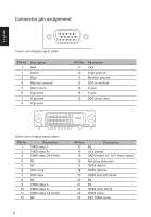
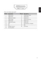
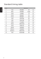
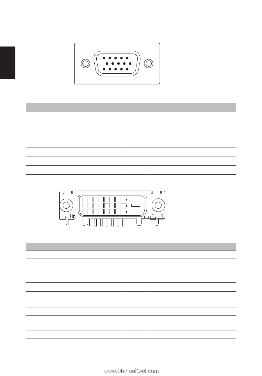
English Connector pin assignment 1 6 11 15-pin color display signal cable PIN No. Description 1 Red 2 Green 3 Blue 4 Monitor ground 5 DDC-return 6 R-ground 7 G-ground 8 B-ground 5 10 15 PIN No. Description 9 +5 V 10 Logic ground 11 Monitor ground 12 DDC-serial data 13 H-sync 14 V-sync 15 DDC-serial clock 24-pin color display signal cable* PIN No. 1 2 3 4 5 6 7 8 9 10 11 12 Description TMDS data 2TMDS data 2+ TMDS data 2/4 shield NC NC DDC clock DDC data NC TMDS data 1TMDS data 1+ TMDS data 1/3 shield NC 4 PIN No. 13 14 15 16 17 18 19 20 21 22 23 24 Description NC +5 V power GND (return for +5 V hsync.vsync) Hot-plug detection TMDS data 0- TMDS data 0+ TMDS data 0/5 shield NC NC TMDS clock shield TMDS clock+ DDC TMDS clock-
-
 1
1 -
2
-
3
-
4
-
5
-
6
-
7
-
8
-
9
-
 10
10 -
 11
11 -
 12
12 -
 13
13 -
 14
14 -
 15
15 -
 16
16 -
 17
17 -
 18
18 -
 19
19 -
 20
20 -
21
-
22
-
23
-
24
-
25
-
26
 |
 |
English
4
Connector pin assignment
1
5
6
10
11
15
15-pin color display signal cable
PIN No.
Description
PIN No.
Description
1
Red
9
+5 V
2
Green
10
Logic ground
3
Blue
11
Monitor ground
4
Monitor ground
12
DDC-serial data
5
DDC-return
13
H-sync
6
R-ground
14
V-sync
7
G-ground
15
DDC-serial clock
8
B-ground
24-pin color display signal cable*
PIN No.
Description
PIN No.
Description
1
TMDS data 2-
13
NC
2
TMDS data 2+
14
+5 V power
3
TMDS data 2/4 shield
15
GND (return for +5 V hsync.vsync)
4
NC
16
Hot-plug detection
5
NC
17
TMDS data 0-
6
DDC clock
18
TMDS data 0+
7
DDC data
19
TMDS data 0/5 shield
8
NC
20
NC
9
TMDS data 1-
21
NC
10
TMDS data 1+
22
TMDS clock shield
11
TMDS data 1/3 shield
23
TMDS clock+
12
NC
24
DDC TMDS clock-