Acer P229HQL User Manual - Page 17
English, Config1, AUX_CH n, Hot Plug Detect, DP Power_Return, DP Power
 |
View all Acer P229HQL manuals
Add to My Manuals
Save this manual to your list of manuals |
Page 17 highlights
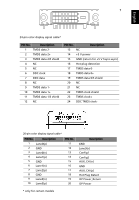
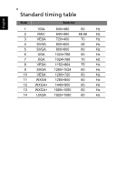
English 7 24-pin color display signal cable* PIN No. Description 1 TMDS data 2- 2 TMDS data 2+ 3 TMDS data 2/4 shield 4 NC 5 NC 6 DDC clock 7 DDC data 8 NC 9 TMDS data 1- 10 TMDS data 1+ 11 TMDS data 1/3 shield 12 NC PIN No. Description 13 NC 14 +5 V power 15 GND (return for +5 V hsync.vsync) 16 Hot-plug detection 17 TMDS data 0- 18 TMDS data 0+ 19 TMDS data 0/5 shield 20 NC 21 NC 22 TMDS clock shield 23 TMDS clock+ 24 DDC TMDS clock- 20-pin color display signal cable* PIN No. Description 1 Lane0(p) 2 GND 3 Lane0(n) 4 Lane1(p) 5 GND 6 Lane1(n) 7 Lane2(p) 8 GND 9 Lane3(n) 10 Lane3(p) PIN No. 11 12 13 14 15 16 17 18 19 20 Description GND Lane3(n) Config1 Config2 AUX_CH (n) GND AUX_CH (p) Hot Plug Detect DP Power_Return DP Power * only for certain models
-
 1
1 -
2
-
3
-
4
-
5
-
6
-
7
-
8
-
9
-
10
-
11
-
 12
12 -
 13
13 -
 14
14 -
 15
15 -
 16
16 -
 17
17 -
 18
18 -
 19
19 -
 20
20 -
 21
21 -
 22
22 -
23
-
24
-
25
-
26
-
27
 |
 |
