Acer P244W User Manual - Page 17
Connecting the docking device (for selected models), Display Data Channel (DDC) - resolution
 |
View all Acer P244W manuals
Add to My Manuals
Save this manual to your list of manuals |
Page 17 highlights
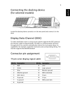
5 Connecting the docking device (for selected models) English Locate the docking device connector on the rear panel and connect it to the dock. Display Data Channel (DDC) To make installation easier, so long as your system supports the DDC protocol, the monitor is able to plug-and-play. The DDC is a communication protocol through which the monitor automatically informs the host system about its capabilities; for example, supported resolutions and corresponding timing. The monitor supports the DDC2B standard. Connector pin assignment 15-pin color display signal cable 1 5 6 10 11 15 PIN No. Description 1 Red 2 Green 3 Blue 4 Monitor ground 5 DDC-return 6 R-ground 7 G-ground 8 B-ground PIN No. Description 9 +5 V 10 Logic ground 11 Monitor ground 12 DDC-serial data 13 H-sync 14 V-sync 15 DDC-serial clock
-
 1
1 -
2
-
3
-
4
-
5
-
6
-
7
-
8
-
9
-
10
-
11
-
 12
12 -
 13
13 -
 14
14 -
 15
15 -
 16
16 -
 17
17 -
 18
18 -
 19
19 -
 20
20 -
 21
21 -
 22
22 -
23
-
24
-
25
-
26
-
27
-
28
 |
 |
