Adaptec AHA-1540 User Manual - Page 3
enable/disable
 |
View all Adaptec AHA-1540 manuals
Add to My Manuals
Save this manual to your list of manuals |
Page 3 highlights
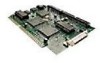
Section Three Installation 3.2.1 SCSI Jumper Configuration Jumper set J1, pin pairs 4, 5 and 6, defines the SCSI address. The SCSI address consists of pin pairs 4, 5, and 6 in the large block of jumper pins located in the upper right hand corner of the PCB. Pin pair 1 is the left most pair of pins. The SCSI address is selected according to the following table. The default address is 7. SCSI Address Jumpers Pin Pair SCSI 4 5 6 Address X XX 0 - XX 1 X- X 2 - -X 3 X X- 4 - X- 5 X- - 6 - -- 7 X = Jumper Installed J1 4 5 6 0 0 0 0 0 0 0 0 0 0 0 0 0 0 0 0 0 0 0 0 0 0 L pin pair 1 3.2.2 SCSI Parity Jumper set J1, pin pair 3, is the parity enable/disable jumper. The SCSI parity jumper, pin pair 3 is located in the large block of jumper pins located in the upper right hand corner of the PCB. Pin pair 1 is the left most pair of pins. The SCSI parity checking is disabled if this jumper is installed. The default is parity checking enabled. 3.2.3 SCSI Terminators RN6 and RN7 are the SCSI terminators. If the AHA-1540 is not the first or the last SCSI device in a string of SCSI devices, or if in-line terminators are used, then both of these resistor networks must be removed. Default is terminators installed. AHA-1540 3 - 2 adaptec
-
 1
1 -
 2
2 -
 3
3 -
 4
4 -
 5
5 -
 6
6 -
 7
7 -
 8
8
 |
 |
