Adaptec AHA-2742T User Manual - Page 24
Default Settings
 |
View all Adaptec AHA-2742T manuals
Add to My Manuals
Save this manual to your list of manuals |
Page 24 highlights
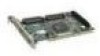
Introduction Location J1 J2 J3 J4 J5 J6 U1 U2 U5 U9 U10 Table 1-1. Host Adapter Components Description External LED Connector Floppy Connector (AHA-2742/2742T only) SCSI Channel A Internal Connector Floppy Enable Jumper (AHA-2742/2742T only) SCSI Channel B Internal Connector (AHA-2740T/2742T only) SCSI Channel A External Connector Floppy Controller (AHA-2742/2742T only) RAM Host Adapter BIOS AIC-7770 Bus Master SCSI Chip AIC-701 Configuration Chip Default Settings Your host adapter is already configured for the majority of EISA class computers. Table 1-2 lists the default settings of your host adapter. Refer to Chapter 3, Configuring the Host Adapter for information on changing any of the settings. Table 1-2. Host Adapter Default Settings Description Interrupt Level Bus Release Time Data FIFO Threshold Host Adapter BIOS Base Address Host Adapter SCSI ID SCSI Bus Parity Check SCSI Selection Timeout SCSI Bus Reset at Power-on SCSI Bus Termination Extended Translation for Drives > 1 GByte Support More Than Two Drives Support Removable Disks as Fixed Disks Default Setting IRQ 11, Level Sensitive 60 BCLKS 100% D8000h Device ID 7 Enabled 256 milliseconds Enabled Enabled Enabled Disabled Boot Device Only 1-7 Adaptec AHA-2740 Series User's Manual Stock Number: 510381-00 / Rev. C (Page 1-7) Print Spec Number: 491709-00 Rev C Current Date: 9/1/93 ECN Date: 9/14/93
-
 1
1 -
2
-
3
-
4
-
5
-
6
-
7
-
8
-
9
-
10
-
11
-
12
-
13
-
14
-
15
-
16
-
17
-
18
-
 19
19 -
 20
20 -
 21
21 -
 22
22 -
 23
23 -
 24
24 -
 25
25 -
 26
26 -
 27
27 -
 28
28 -
 29
29 -
30
-
31
-
32
-
33
-
34
-
35
-
36
-
37
-
38
-
39
-
40
-
41
-
42
-
43
-
44
-
45
-
46
-
47
-
48
-
49
-
50
-
51
-
52
-
53
-
54
-
55
-
56
-
57
-
58
-
59
-
60
-
61
-
62
-
63
-
64
-
65
-
66
-
67
-
68
-
69
-
70
-
71
-
72
-
73
-
74
-
75
-
76
-
77
-
78
-
79
-
80
-
81
-
82
-
83
-
84
-
85
-
86
-
87
-
88
-
89
-
90
-
91
-
92
-
93
-
94
-
95
-
96
-
97
-
98
-
99
-
100
-
101
-
102
-
103
-
104
-
105
-
106
-
107
-
108
-
109
-
110
-
111
-
112
-
113
-
114
-
115
-
116
-
117
-
118
-
119
-
120
-
121
-
122
-
123
-
124
-
125
-
126
-
127
-
128
-
129
-
130
-
131
-
132
-
133
 |
 |
