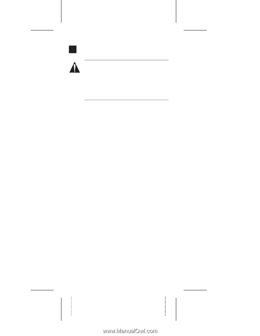
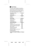
Adaptec AHA-3940U Getting Started Guide - Page 5
Connecting SCSI Devices - aha 3940uw scsi
 |
View all Adaptec AHA-3940U manuals
Add to My Manuals
Save this manual to your list of manuals |
Page 5 highlights
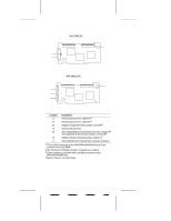
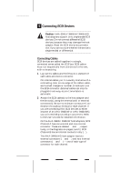
5 Connecting SCSI Devices Caution: AHA-3940U/3940UW/3940UWD host adapters support only single-ended SCSI devices. Do not connect differential SCSI devices, because they may damage the host adapter. Read the SCSI device documentation if you are not sure whether the device is single-ended or differential. Connecting Cables SCSI devices are cabled together in a single, connected series called the SCSI bus. SCSI cables must run sequentially from one device to the next, with no branching. 1 Lay out the cables and find the pin-1 element of each cable and device connector. On internal cables, pin 1 is usually marked with a contrasting color on one edge of the ribbon cable, and a small triangle or number 1 marks pin 1 on the SCSI connector. External cables can only be plugged in one way, so pin-1 orientation is automatic. 2 Attach the SCSI cable(s) to the host adapter and the device(s), using the internal and/or external connector(s). Be sure to maintain correct pin-1 orientation throughout the bus for each channel. If you are connecting 8-bit SCSI devices to either channel of an AHA-3940UW or AHA-3940UWD, you will need 68-pin-to-50-pin converters. Refer to the User's Guide for detailed information. On the AHA-3940U/3940UW host adapters, SCSI Channel A has one external and one internal connector. These are labeled J5 and J1, respectively, in the diagrams on pages 1 and 2. SCSI Channel B has an internal connector only (J2). The AHA-3940UWD host adapter has two external connectors (J7 and J5) and two internal connectors (J1 and J2) - one of each type of connector for each channel. 5 AAAAAAAAAAAAAAAAAAPPCAAAAAAaruHiAAArrntAAAArtAAAeN-SAAAn3uAAApt9mAAAeD4AAAcbAAA0aeAAANtUerAAAu::/AAA3mAAA519AAA11b4AAA1/eAAA010rAAAU4:4AAA/04WAAA9-AAA960AAA/43AAA059AAA,6AAA4R8AAA0e-AAAU0vAAA0AAA.WAAABAAADEAAAAAACIAAAnNAAAsAAAtDAAAaAAAlalAAAtaAAAetAAA:i1oAAAAAA1nAAA/G1AAAAAA8uAAA/i9AAAdAAA6eAAAAAAAAAAAAAAAAAAAAAAAAAAAAAAAAAAA
-
 1
1 -
 2
2 -
 3
3 -
 4
4 -
 5
5 -
 6
6 -
 7
7 -
 8
8 -
 9
9 -
 10
10 -
 11
11 -
12
-
13
-
14
 |
 |