Airlink AGSW801 User Manual - Page 4
Install the Gigabit Switch - 8 port gigabit switch
 |
View all Airlink AGSW801 manuals
Add to My Manuals
Save this manual to your list of manuals |
Page 4 highlights
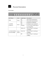
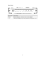
2 Install the Gigabit Switch 1. Operating Environment This switch must be installed and operated within the limits of specified operating temperature (32-1310F) and humidity (10-90% Non-condensing). Do not place objects on top of the unit. Do not obstruct any vents at the sides of the unit. Do not position the unit near any heating source such as heater, radiator, or direct exposure to sun. Prevent entering of water and moisture into the unit. If necessary, use dehumidifier to reduce humidity. 2. Connecting to network devices The RJ-45 ports on the switch support Auto-MDI/MDI-X function which allows using straight-through or cross-over type cables to connect this switch to workstation or hub. Connect one end of the network cable to the RJ-45 port on the rear panel, and connect the other end of the network cable to the RJ-45 port on the network device. Follow the same procedure to connect all the RJ-45 ports of the switch. The UTP network cables must be four pairs Category 5 standard for 1000Mbps data transmission; two pairs Category 5 for 100Mbps data transmission; two pairs Category 3, 4 or 5 standards for 10Mbps data transmission. Maximum length, using UTP cable, between the switch and connected device is 100 meters (300ft). Once the network cable is connected to both ends and the attached network device is powered on, the green LNK/ACT LED should be lit. 3. Connecting the power Connect the output end of the power adapter to the power connector on the rear panel of the switch. Connect the power adapter to the power outlet. The green Power LED on the front panel should be lit. 3
-
 1
1 -
 2
2 -
 3
3 -
 4
4 -
 5
5
 |
 |
