Alpine HCE-C104 Owners Manual - Page 3
Chec:k, Accessory PartsNerlflez las accessolras/Compruebe los accesorios, Installation Location/ - extension cable only
 |
View all Alpine HCE-C104 manuals
Add to My Manuals
Save this manual to your list of manuals |
Page 3 highlights
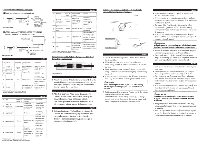
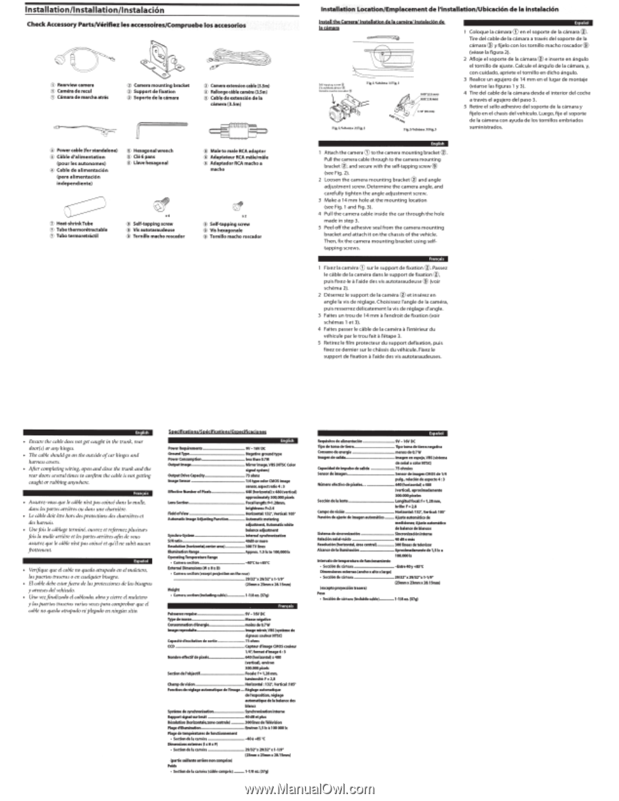
lnstallation/lnstallation/lnstalacion Chec:k Accessory PartsNerlflez las accessolras/Compruebe los accesorios (j) Rearview camera CD Camero de recul CD Cilmara de marcha atras @ Camera mounting bracket @ Supportdefixation @ Soporte de Ia climara @ Camfl'a extension cable ll.Sm) @ Rallonge cible camera (3.5m) @ CabI, de extensiOn de Ia cilmera (3.5m) @ Power cable {for standalone) @ Cible d 'alimentation (pour les autonomes) @ Cable de alime ntaciOn (para alime nta tiOn independie nte) @ Hexagonal wrench (~ Cle6 pans ® llave hexagonal ® Male to male RCA adaptor ® Adaptateur RCA mile/mile ® Adaptador RCA macho a macho CV Heat-shrinkTube (j) Tubethermoretractable 0 Tubo termoretr
-
 1
1 -
 2
2 -
 3
3 -
 4
4 -
 5
5 -
 6
6 -
 7
7 -
 8
8
 |
 |
lnstallation/lnstallation/lnstalacion
Chec:k
Accessory PartsNerlflez las accessolras/Compruebe los accesorios
(j)
Rearview camera
CD
Camero
de recul
@
Camera mounting bracket
@
Supportdefixation
@
Camfl'a
extension
cable
ll.Sm)
@
Rallonge
cible
camera
(3.5m)
@
Cab
I,
de
extensiOn de
Ia
CD
Cilmara
de marcha
atras
@
Soporte de Ia climara
cilmera (3.5m)
@
Power cable
{for
standalone)
@
Cible
d'
alimentation
(pour
les
autonomes)
@
Hexagonal
wrench
(~
Cl
e6
pans
®
Male
to
male
RCA
adaptor
®
Adaptateur
RCA
mile/mile
®
Adaptador
RCA
macho a
®
llave
hexagonal
@
Cable
de
alime
ntac
i
On
(para
alim
e
nt
a tiOn
independi
e nte)
macho
CV
Heat-shrinkTube
(j)
Tubeth
ermoretractable
0
Tubo
termoretr<ilctil
®
Self-tapping screw
®
Vis
autotaraudeuse
®
Self-tapping screw
®
V
is
hexagonale
®
Tornillo macho
roscdor
®
Tornillo macho roscador
Ensuu
th
e
cabl
e
does
not get
caught
in
the
trunk,
rear
door(s
) or any
hinges
.
Th
e c
abl
e shoultl go
on
th
e outside
ofmr
hing
es and
harn
es
s
cover
s.
After
completing
wiring
;
op
en
and
clos
e
the
trunk and t
he
re
ar
doors
several
times
to
confirm
th
e
cable
is
not getting
caught
or
rubbing
anywhere.
Assurez
-
vou
s
que
le
cclb/e
nest
pas
coind
dans
Ia
mafic
.
dans
fes
portes
arriere
s
ou
dans
une
charnil.
~
re.
Le
cclb/
e d
oit
e
tr
e
ho
rs
des
prot
e
ctions
des
'-'harni
b
es
et
desharnais.
Une
fois
le
ctlblage
term
in
C,
ouvrez et
rejl:rmez
plusieurs
fois
Ia
malle
arrier
e
etl
es
por
te
s ar
ri
e
res
a
fin de
vous
assurez
qu
e
le
cable
nest
pas
coince
et
qu'il ne
subit
aucun
frottement .
Verifique
qu
e
ef
cabl
e
no
queda
atrapado
en
e/
ma/e
te
r
o,
las
pu
e
rtas
tras
er
as
o en
cua
lquier
bisagra.
El
cable
debe
est
ar
fuera
de
las
protecciones
de
las
bist~gras
y
t~rne
s
e
s
d
el
vehfcul
o.
Una
vez
fint~lizado
el
cableado,
abray
cier
re e/
maletero
y
las
pu
er
tas
tr
as
e
ras
varias
vec
es
p11Ya
comprobt~r
tJUC
el
cable
no
queda
atrapado
ni
pfegado
en
ningUn
sitio.
Spes:jfjcotjons/
Sptcjficatjon$}Espcsjfjcadpnes
'-t~hqWI'ements
---
.............
tV
- 16VDC
Ground
Type
..........
___
,,
....
..
.................
-
..
Ne~v
e
ground
type
Powet
consumption
..
- ...
..
........
..
-
..
less thlln0.7W
OUCputlm.,e
.....
_,,,_
....
..
...
-
..
MinOJ
imlge,V8S I
NTSCCoiOJ
si
gn•l system)
Output
Dri
n
C.p.aty
....
..
........... .
-
..
75
ohm
s
.....
-
..
114typetofOJCMOSim•ge
um
OJ
,
tspKtrltio4:l
..
640!hori:ontll) x 480(verti
c.l
)
•ppm
imt tely 300,000
pixel
s
Lens5Ktion...
......
....
fotlflength:f::1.
24mm.
brightness:F=-2.4
FietdofVi-
............
Horizontii:132",Vtrt
iui:
10S"
Automtlic
lmtgt
Adjusting Function ...
..
..........
Automtti<
mett~ing
•djustment.Automlticwhite
bll1nce
tdjudmtnt
Syndwo-System
....
..
................
...
lntemlll
syndwoniz..lion
S/
Nrltio
...........
..
_
40d80JmOJe
RHOIIIIion
(horizonttl,center
tr
N).
..
....
100
TV
lines
ll
lumiMtlon
Rtngt
......
Approx.
l.Sb
to
100,000 lx
Op«1ting
Ttmp«ltlft
R
-.ge
•
Cll
m
ense
ctkln
.......
_
......
M
....................
..
.....
-40"
Cto
+
8S
"C
Extt~DII
Dimtnsiom
(W
x
Hx
0)
•
Cll
mu
~
sa
ctlon
(exce
pt projection
ontht
ru
t )
..
........
29/32
~x
2
91
l2
"
x
1·1/9"'
(
llmm
x 23mmx2&.1Smm)
Weight
• Camera
se
ction tlndudlng u
bl
e)
...............
1-1/
So:r.
(37g
)
f'uiS51ncerequise
_
......
.
Typedem155e-
..
~
....
Consommltion d'entrgie
lmlgereprocklitt
..........
..
H
..
.............
-
..
tV
-
16VOC
.....
..
.....
,_
...
M•sst
Mgative
..
.......
.....
....
moin5
de
0,1
w
..
...
....
tmagemiroir,
V8S
tsystime
de
si
gnawccouleurNTSC
)
C1p1
ci
te d'excit11iondtsOJ1ie
......
75otwns
ceo
..
..
...............
-
....
c.pttur
d1m~gt
CMO
S
coul.ur
1/4:
fonnttdim•ge4:3
.........
..
...............
640 (hori:rontll
)x
48CI
Sectiondel'objKtif
..
...
(verli<lt), environ
lOO.OOOpi
xets
..........
fotlf
t:
f=1
,28
mm,
luminosit
e:
F
=
2.8
Champ
de
vision
..
__
..
.....
Horizonttl : 13
2"
, Vtrticll :
los
·
Fonction
de
rfgl1gt
1utomltique
de
11mege
..
Rfgl1ge
tutomlti!fte
de l'txposilion.r'sll191
1utomltiqut
de
Ia
bll1nce
dH
bl
ana
Sy
stimtdesynd.oniAtion
.......
......... .....
-
..
....
SynchronisalionintlfM
Rlpport
si
gnt l
sw
bruit
..
..
....
....
40dBet
plus
RHolution (horizontllt,
mne
centrillt)
...
..
300
lint
s
dt
Television
Pllgt
d'iflun~inltion
....
..
....
&Mron
1.5
be
•1
00 000
lx
Pllgt
de
tempWaturft
dt
fondionnement
•
Se
ctfondel~
a
m
t!
ra
..
.-
......
-4041
+8S "C
Dimenslonstlltemfs(l x HxPl
• St
ctfondelacam
l
rl
-
tp
lrti
tMilllfltetrritrtnon
compri
st)
,.,;
..
....
..
...
29
/l
rx
29/l2"x1-
11
9"
(23mm
x
23mm
x 2
8.
1Smml
• St
criondel•umlti(dbkcompri
s)
..........
1-1/
8oL(37g
)
Installation Location/Emplacement
de
11nstallation/Ubicacion
de
Ia
instalacion
Install
tbt
C
omtro
/ lnltol!otjpn
si
t
Ia
cam;ro
t
!nstolocjQn
sic
luimlu
~~~
:!
~
~:
:~~:;,
,
Tor
o
l
l
l
om"
~
O
t
OI<ador
@
Ftg.I/Sc
h
<'
m• ll
l'ig.l
Fig
.
2/Sdle
n
>~
2/
Fig
.
2
1
Attach the camera
CD
to the camera mounting brack
et@.
Pu
ll
the camera ca
bl
e through to the camera
mo
unting
bracket
@,
and secu
re
wi
th the
se
lf
-tapp
in
g
sc
r
ew®
(see Fig.
2).
2
Loosen the
came
ra m o
untin
g
br
ac
ke t ® a
nd
a ng le
a
dju
stment scr
ew
. Det
er
mine
th
e
ca
mera angle, a
nd
ca
refully
tig
ht
e n
th
e angle a
dju
s
tm
e
nt
screw.
3
Make a
14
mm
hole at
th
e mo
untin
g l
oca
t io n
(see
Fi
g.
1
a
nd
F
ig
.
3).
4 P
ull
th
e camera
cab
le i
ns
i
de
the
car thro
ugh
th
e
ho
le
m
ade
in st
ep
3.
5
Pee
l off
th
e
ad
hesive
sea
l from t
he
ca
m
era
mou
nti
ng
br
ac
ket a
nd
a
tt
a
ch
it o n
th
e ch
ass
is of
th
e
ve
hicle.
The n,
fi
x
th
e
ca
m
era
mo
unting bracket using
se
lf-
t
ap
pi
ng
screws.
1
Fi
xez
Ia c
am
e ra
CD
sur le support de f
ix
ation
@ . Passez
le cable de Ia cam
era
dans le su
pp
ort de fixation
@,
puis
fi
xez-le
a
!'ai
de
des
vis a
ut
otara
ud
euse
®
(voir
schema
2) .
2
oese
rr
ez
le s
upp
o
rt
de
Ia cam
era®
e t in
se
r
ez
e n
a ng le Ia v is d e r
eg
l
age.
Cho isi
ssez
I'
a ng le de
Ia
camera,
pu
is
r
esse
rr
ez
df
di
catement Ia vis de regl
age
d'angle.
3
Fa it
es
un
trou
de
14
mm
a
l'e
ndr
o it d e fixa
ti
o n (vo
ir
schemas 1
et
3).
4
Fa it
es
p
asse
r le ca
bl
e de Ia
ca
m
era
a
l'inte
ri
eur du
ve
h icu le pa r le
trou
fa it
a
l'etape
3.
5 Re
ti
rez le film p ro t
ec
teur
du
s
upport
def
ixati
on,
puis
fix
ez
ce
de
rni
er
sur le chassis du vehic
ul
e.
Fi
xez
le
su
ppor
t
de
fixation
a
I'a i
de
d
es
vis a
ut
otarau
de
u
ses
.
Requisitosdtalimtnt.ciOn
..
.
..
.........................
..
9V
-16V
DC
lipo
de
tOIM
de1ierr1 _
,,
_
....
....
...
....
.
..
....
......
...
lipo
tom•
dt
lierre
negltiv•
C
-.modetner9i1
-
..
-
.......
..
......................
menosd
t 0,7W
lmagtndf
sali
dl
..
~···
-
--
.
lmlgtn
fn
esptjo,
V8S
(5i
stftftl
deStil!
tlt
colorNTSCI
C.p1cidlddtimpulsodt
Wid•
....
75 ohmios
S.nsoJ
df
im
tgtn
.,,,_
..
....
.
..
Sensor
dt
im
1gen
CMOS
de
1/4
pulg., rett
ci6ndetspteto4
: l
NUmtro
•tivodt
pixfiH
....
..........
..
. 640{hori:ontll)
x 480
{
vertial
),l
proximtdtment
e
StcciOndfllltm
f
lOO
.
ooop
x
etH
.....................
-
...
Longituclfocal:f=1,28mm.
bri
lo:
F=2.8
C.mpodtvisi6n..
..
......
Horizontal:
13
2",
Vtrtic1l: 105"
ftlnciOndti~deinl•genMJtomitico
........
Ajustt
aut
oml
licode
m~ldones;AjusttlutomltiCO
dfbll
l
n<
fdt
bllnCOS
Sistem1
de
s
inu
on
iz..ciOn
...........................
..
- .
SinaoniDdOninttml
Ret•
d Onseiiti-Ndo -
....
...
....
-
.40dBomls
R1501u<i0n
thorizontiL
lru
ctntr
-'
)
....
..
...
..
....
300linu
s
dt
lfltvisor
Alcanctdf
I•
illftlinaOOn
......
_
..
_
..........
..
-
..
..
Apr
oxinM
dlmtntt
df 1,
51
x •
lOO.OOOix
Dim
ensi
-stxttrDIS
{Incho x •
lto x l
1r
go)
•
Se
cdOnde d mar
a-
...........
- 29{l
2"
x29/
l2"x1
·1/9"
{uceptopJoyf«iintruere
)
....
{
Dmmx2lnn
x 28.1Smm)
• Se«<
On
de d
mara (induklo
t~bl
t)
. ............
1-
1
/S
oz.
(l7gl
1
Co lo
qu
e Ia cilma ra
G)
e n e l
sopo
rt
e de Ia ct.ma ra
®.
Tir
e
de
l cable
de
Ia
c
am
a
ra
a tr
aves
del s
oport
e
de
Ia
camara
®
y
ffj
e lo
co
n l
os
tornillo m
ac
ho
roscador
®
(
vease
Ia figura
2).
2 A
fl
oje el sop
or
te de
Ia
ca
ma
ra ®
e
i
nser
te en angulo
e l to rn i
ll
o de aju
ste
. Ca
kul
e el
il
ngulo de Ia cama
ra
, y,
co
n cuidad
o,
apriete el tornillo en dicho ilng
ul
o.
3
R
ea
lice un
ag
uj
ero
de
14
mm
e n e
llu
ga
r
de
mo
nt
aje
(
veanse
las
fi
guras
1
y
3).
4
Tir
e d e l c
ab
le de Ia
cci
m a ra
des
d e e l i
nt
e
ri
or del
cac
he
a tr
ave
s el ag
uj
ero del p
aso
3.
5
Retire el
se
ll
o a
dh
es
i
vo
del soporte
de
Ia cilmara y
ff
je lo e n e l
chas
is
de
l
ve
hlc
ul
o.
Lu
ego
,
fi
je el sop
or
te
de Ia ca
mer
a
co
n ay
ud
a de l
os
to rnill
os
embriad
os
s
umin
is
tr
ados.