Alpine PDR-M65 Owners Manual - Page 4
Installation - amplifier
 |
View all Alpine PDR-M65 manuals
Add to My Manuals
Save this manual to your list of manuals |
Page 4 highlights
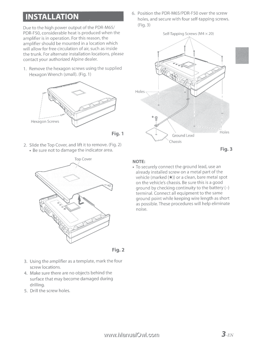
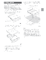
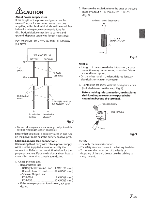
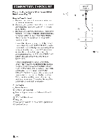
INSTALLATION Due to the high power output of the PDR-M65/ PDR-FSO, considerable heat is produced when the amplifier is in operation. For this reason, the amplifier should be mounted in a location which will allow for free circulation of air, such as inside the trunk. For alternate installation locations, please contact your authorized Alpine dealer. 1. Remove the hexagon screws using the supplied Hexagon Wrench (small). (Fig. 1) 6. Position the PDR-M65/PDR-FSO over the screw holes, and secure with four self-tapping screws. (Fig. 3) Self-Tapping Screws (M4 x 20) Fig. 1 2. Slide the Top Cover, and lift it to remove. (Fig. 2) • Be sure not to damage the indicator area. ~ Gcound leod Chassis Holes Fig.3 NOTE: • To securely connect the ground lead, use an already installed screw on a metal part of the vehicle (marked (*))or a clean, bare metal spot on the vehicle's chassis. Be sure this is a good ground by checking continuity to the battery H terminal. Connect all equipment to the same ground point while keeping wire length as short as possible. These procedures will help eliminate noise. Fig. 2 3. Using the amplifier as a template, mark the four screw locations. 4. Make sure there are no objects behind the surface that may become damaged during drilling. 5. Drill the screw holes. 3 -EN
-
 1
1 -
 2
2 -
 3
3 -
 4
4 -
 5
5 -
 6
6 -
 7
7 -
 8
8 -
 9
9 -
 10
10 -
11
-
12
-
13
-
14
-
15
-
16
-
17
-
18
-
19
 |
 |