Alpine R-A75M Owners Manual English - Page 17
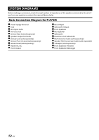
Basic Connection Diagram for R-A60F
 |
View all Alpine R-A75M manuals
Add to My Manuals
Save this manual to your list of manuals |
Page 17 highlights
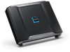
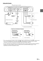
Basic Connection Diagram for R-A60F Power Supply Terminal Fuse RCA Input Jacks Pre-Out Jacks Remote Bass Control (optional) Speaker Output Terminals Battery Lead (sold separately) Remote Turn-On Lead (sold separately) Ground Lead (sold separately) Head Unit, etc. Front Output Rear Output Subwoofer Output Front Speakers Rear Speaker Subwoofer Dual Voice Coil Subwoofer RCA Extension Cable (sold separately) Speaker-RCA Conversion Cable (sold separately) Y-Adapter (sold separately) Front Speakers (Tweeter) Front Speakers (Midrange) For R-A60F, change the Input Channel Selector Switch ( ) setting according to the number of channels of the speaker input. Input Channel Selector Switch (CHANNEL-3/4) 4-Channel Input: 3/4 2-Channel Input: 1/2 4 Speaker System Speaker Input Level Switch [LO] Remote Turn-On Lead Head Unit, etc. * If the connected head unit does not have a Speaker Output and RCA Extension Cable ( ) cannot be used, you can use the Speaker-RCA Conversion Cable ( ) (sold separately). For details on how to make a connection, see "About Connecting to the Speaker Input Level System" (page 19). 15-EN
-
 1
1 -
2
-
3
-
4
-
5
-
6
-
7
-
8
-
9
-
10
-
11
-
 12
12 -
 13
13 -
 14
14 -
 15
15 -
 16
16 -
 17
17 -
 18
18 -
 19
19 -
 20
20 -
 21
21 -
 22
22 -
23
-
24
 |
 |
