Alpine R2-SB10V-BNDL Owners Manual - Page 16
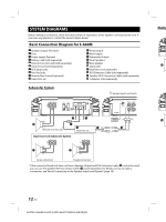
Basic Connection Diagram for S-A32F
 |
View all Alpine R2-SB10V-BNDL manuals
Add to My Manuals
Save this manual to your list of manuals |
Page 16 highlights
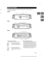
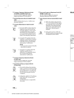
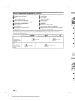
Basic Connection Diagram for S-A32F Speaker Output Terminals Fuse Power Supply Terminal Battery Lead (sold separately) Remote Turn-On Lead (sold separately) Ground Lead (sold separately) RCA Input Jacks Pre-Out Jacks Remote Bass Control (optional) Head Unit, etc. Front Output Rear Output Subwoofer Output Front Speakers Rear Speaker Subwoofer Dual Voice Coil Subwoofer RCA Extension Cable (sold separately) Speaker-RCA Conversion Cable (sold separately) Y-Adapter (sold separately) 4 Speaker System Speaker Input Level Switch 2 Spea [LO] Remote Turn-On Lead Head Unit, etc. 2 Spea * If the connected head unit does not have a Speaker Output and RCA Extension Cable ( ) cannot be used, you can use the Speaker-RCA Conversion Cable ( ) (sold separately). For details on how to make a connection, see "About Connecting to the Speaker Input Level System" (page 18). 14-EN ALPINE S-A60M/S-A32F/S-A55V 68-35792Z59-A (EN/FR/ES)
-
 1
1 -
2
-
3
-
4
-
5
-
6
-
7
-
8
-
9
-
10
-
 11
11 -
 12
12 -
 13
13 -
 14
14 -
 15
15 -
 16
16 -
 17
17 -
 18
18 -
 19
19 -
 20
20 -
 21
21 -
22
-
23
-
24
-
25
-
26
-
27
-
28
-
29
-
30
-
31
-
32
-
33
-
34
-
35
-
36
-
37
-
38
-
39
-
40
-
41
-
42
-
43
-
44
-
45
-
46
-
47
-
48
-
49
-
50
-
51
-
52
-
53
-
54
-
55
-
56
-
57
-
58
-
59
-
60
-
61
-
62
-
63
-
64
-
65
-
66
-
67
-
68
 |
 |
