Amana AGR5330BAS Installation Guide - Page 8
Make Gas Connection
 |
View all Amana AGR5330BAS manuals
Add to My Manuals
Save this manual to your list of manuals |
Page 8 highlights
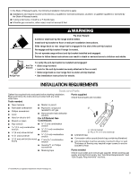
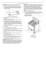
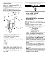
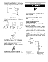
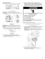
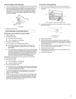
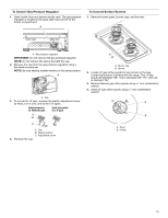
3. Determine and mark centerline of the cutout space. The mounting can be installed on either the left side or right side of the cutout. Position mounting bracket against the wall in the cutout so that the V-notch of the bracket is 95⁄8" (24.6 cm) from centerline as shown. B Centerline Make Gas Connection WARNING A A. 95⁄8" (24.6 cm) B. Bracket V-notch 4. Drill two ¹⁄8" (3 mm) holes that correspond to the bracket holes of the determined mounting method. See the following illustrations. Floor Mounting Rear position Wall Mounting Front position Diagonal (2 options) Explosion Hazard Use a new CSA International approved gas supply line. Install a shut-off valve. Securely tighten all gas connections. If connected to LP, have a qualified person make sure gas pressure does not exceed 14" (36 cm) water column. Examples of a qualified person include: licensed heating personnel, authorized gas company personnel, and authorized service personnel. Failure to do so can result in death, explosion, or fire. Typical flexible connection 1. Apply pipe-joint compound made for use with LP gas to the smaller thread ends of the flexible connector adapters (see B and F in the following illustration). 2. Attach one adapter to the gas pressure regulator and the other adapter to the gas shut-off valve. Tighten both adapters, being certain not to move or turn the gas pressure regulator. 3. Use a 15⁄16" (2.4 cm) combination wrench and an adjustable wrench to attach the flexible connector to the adapters. IMPORTANT: All connections must be wrench-tightened. Do not make connections to the gas regulator too tight. Making the connections too tight may crack the regulator and cause a gas leak. Do not allow the regulator to turn when tightening fittings. 5. Using the Phillips screwdriver, mount anti-tip bracket to the wall or floor with the two #12 x 15⁄8" (4.1 cm) screws provided. 6. Move range close enough to opening to allow for final gas and electrical connections. Remove shipping base, cardboard, or hardboard from under range. 7. Move range into its final location, making sure rear leveling leg slides into anti-tip bracket. 8. Move range forward onto shipping base, cardboard, or hardboard to continue installing the range using the following installation instructions. A B D C A. Pressure regulator connection fitting B. Use pipe-joint compound. C. Adapter D. Flexible connector E F G H E. Adapter F. Use pipe-joint compound. G. Manual shut-off valve H. ½" (1.3 cm) or ¾" (1.9 cm) gas pipe 8
-
 1
1 -
2
-
 3
3 -
 4
4 -
 5
5 -
 6
6 -
 7
7 -
 8
8 -
 9
9 -
 10
10 -
 11
11 -
 12
12 -
 13
13 -
14
-
15
-
16
 |
 |
