Apple M9745LL User Guide - Page 17
and Your Server at a Glance-Interior on for detailed views.
 |
UPC - 718908876725
View all Apple M9745LL manuals
Add to My Manuals
Save this manual to your list of manuals |
Page 17 highlights
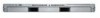
® On/standby button and light Press to turn on the server. Enclosure lock and lock status light The lock secures the enclosure and drive modules in the server. It can be locked and unlocked with the enclosure key supplied with the server. An option in the Security pane of System Preferences lets you inactivate a connected keyboard and mouse when the enclosure lock is engaged. This option is turned off by default. See "Controlling Access to a Connected Keyboard and Mouse" on page 59 for details. When the enclosure lock is locked (the light is on), the server may not recognize peripheral devices such as a keyboard, mouse, or storage device. Unlock the lock to use those devices. System identifier button and light The system identifier light turns on if a problem is detected. It also can be turned on manually by pressing the button. This indicator is useful for locating a particular unit in a rack with multiple servers. A duplicate system identifier button and light are on the back panel. FireWire 400 port Provides a FireWire 400 connection on the front of the server. There are also two FireWire 800 ports on the back panel. The enclosure lock must be unlocked for the server to recognize some devices connected to this port. (See "FireWire Specifications" on page 86 for information about FireWire ports and connectors.) G Ethernet link lights Two lights indicate the connection status of each of the server's two built-in Ethernet ports. System activity lights Two rows of eight lights indicate system activity.The rows of lights operate independently to show each processor's activity. These lights also show the options in front panel mode; see "Entering Firmware Boot Commands From the System's Front Panel" on page 63 for details. Drive module and lights The removable serial ATA (SATA) drive module contains the server software and has lights showing operating status and disk activity. You cannot install additional drive modules in this Xserve G5 model. Note: The back panel and interior of the cluster node system are mostly the same as those of the standard system. See "Your Server at a Glance-Back Panel" on page 12 and "Your Server at a Glance-Interior" on page 14 for detailed views. Chapter 1 Xserve G5 Overview 17
-
 1
1 -
2
-
3
-
4
-
5
-
6
-
7
-
8
-
9
-
10
-
11
-
 12
12 -
 13
13 -
 14
14 -
 15
15 -
 16
16 -
 17
17 -
 18
18 -
 19
19 -
 20
20 -
 21
21 -
 22
22 -
23
-
24
-
25
-
26
-
27
-
28
-
29
-
30
-
31
-
32
-
33
-
34
-
35
-
36
-
37
-
38
-
39
-
40
-
41
-
42
-
43
-
44
-
45
-
46
-
47
-
48
-
49
-
50
-
51
-
52
-
53
-
54
-
55
-
56
-
57
-
58
-
59
-
60
-
61
-
62
-
63
-
64
-
65
-
66
-
67
-
68
-
69
-
70
-
71
-
72
-
73
-
74
-
75
-
76
-
77
-
78
-
79
-
80
-
81
-
82
-
83
-
84
-
85
-
86
-
87
-
88
-
89
-
90
-
91
-
92
-
93
-
94
-
95
-
96
 |
 |
