Ariens Deluxe 28 Owners Manual - Page 10
Unfold Upper Handlebar Assembly, Connect Headlight Wire Harness, Install Trigger Cable Assembly, Speed
 |
View all Ariens Deluxe 28 manuals
Add to My Manuals
Save this manual to your list of manuals |
Page 10 highlights
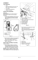
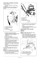
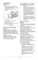
Unfold Upper Handlebar Assembly (Figures 7 and 8) 1. Rotate the handlebar into operating position. NOTICE: Be careful not to damage cable spring hooks when rotating handlebar upward. . 4 1 1 2 3 4 1. Wire Harness 2 2. Cable Tie 3. Cable Anchor 3 4. Engine Electrical Plug Figure 8 1. Handlebar Hardware 2. Shift Rod Hardware 3. Shift Rod 4. Speed Selector Lever Figure 7 2. Install the remaining handlebar hardware attaching the upper handlebar assembly to the lower handlebar (Figure 5). 3. Tighten all hardware. 4. Remove packaging around shift rod. 5. Rotate shift rod into place and tighten hardware. 6. Connect shift rod to speed selector arm and adjust as specified in Speed Selector Adjustment on page 29. 7. Adjust attachment cable as specified in Attachment Clutch/Brake Adjustment on page 29. 8. Adjust the traction cable as specified in Traction Drive Clutch Adjustment on page 31. Connect Headlight Wire Harness (Figure 8) NOTICE: The headlight wire harness comes attached to the upper handlebar assembly. 1. Route the wire harness along the interior of the right side handlebar. 2. Connect to the engine electrical plug. 3. Press cable anchor into mounting hole in the frame near the engine electrical plug. 4. Secure the wire harness to the handlebars using the cable ties attached to the wire harness. Install Trigger Cable Assembly (921023) (Figure 9) NOTICE: Trigger cable assembly comes attached to the Sno-thro unit. 1. Attach remote trigger cable assembly to upper handlebar assembly using one 1/4" x 1-1/2 oval head machine screw (Figure 3, Item 14) and one 1/4" locking washer (Figure 3, Item 15) (Figure 9). 2 3 1 1. Trigger Cable Assembly 2. Oval Head Machine Screw 3. Internal Locking Washer Figure 9 EN - 10
-
 1
1 -
2
-
3
-
4
-
 5
5 -
 6
6 -
 7
7 -
 8
8 -
 9
9 -
 10
10 -
 11
11 -
 12
12 -
 13
13 -
 14
14 -
 15
15 -
16
-
17
-
18
-
19
-
20
-
21
-
22
-
23
-
24
-
25
-
26
-
27
-
28
-
29
-
30
-
31
-
32
-
33
-
34
-
35
-
36
-
37
-
38
-
39
-
40
-
41
-
42
 |
 |
