Ariens Platinum 30 Owners Manual - Page 21
TO STOP IN AN EMERGENCY, Check Axle Lock Pins 921024 - engine manual
 |
View all Ariens Platinum 30 manuals
Add to My Manuals
Save this manual to your list of manuals |
Page 21 highlights
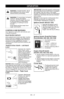
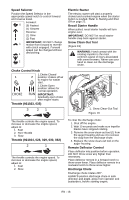
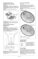
IMPORTANT: DO NOT OVERFILL! This equipment and/or its engine may include evaporative emissions control system components, required to meet EPA and/or CARB regulations, that will only function properly when the fuel tank has been filled to the recommended level. Overfilling may cause permanent damage to evaporative emissions control system components. Filling to the recommended level ensures a vapor gap required to allow for fuel expansion. Pay close attention while filling the fuel tank to ensure that the recommended fuel level inside the tank is not exceeded. Use a portable gasoline container with an appropriately sized dispensing spout when filling the tank. Do not use a funnel or other device that obstructs the view of the tank filling process. 6. Replace fuel cap and tighten. 7. ALWAYS clean up spilled fuel. Fuel Shut-Off Valve (921023, 035) IMPORTANT: The fuel shut-off valve MUST be in the closed position prior to transporting the unit. The fuel shut-off valve 1 has two positions: Open Position (1): Use this position to run the unit. Closed Position (2): Use this position to service, transport, or store the unit. 2 Fuel Shut-Off Valve (921024, 028, 029, 030, 032) IMPORTANT: The fuel shut-off valve MUST be in the closed position prior to transporting the unit. The fuel shut-off valve has two positions: OFF 2 1 ON Open (1): Use this position to run the unit. Closed (2): Use this position to service, transport, or store the unit. PRE-START 1. Frozen Impeller IMPORTANT: Before starting engine, check impeller to be sure it is not frozen. To check impeller: 1. With ignition key switch in "Stop" position, squeeze Attachment Clutch Lever to Engaged position. 2. Pull Recoil Starter Handle. 3. If Impeller is frozen, (cannot pull Starter Handle) move unit to a heated area and thaw to prevent possible damage. 2. Check Function of Clutches If clutches do not engage or disengage properly, adjust or repair before operation. See Attachment Clutch/Brake Adjustment on page 29 and Traction Drive Clutch Adjustment on page 31. 3. Check Dual Handle Interlock Without the engine running, press down (engage) both clutch levers. Release attachment clutch lever. Attachment clutch should remain engaged until traction clutch lever is released, then both clutches must disengage. If clutches do not engage or disengage properly, adjust or repair before operation. See Attachment Clutch/Brake Adjustment on page 29 and Traction Drive Clutch Adjustment on page 31. 4. Check Axle Lock Pins (921024) Use the axle lock pins to lock or unlock the wheels. Lock both wheels to increase traction; unlock one wheel to allow for easier turning of the unit. 5. Check Skid Shoes Check and adjust Skid Shoes (See Skid Shoes on page 27). Allow 1/8" (3 mm) between scraper blade and hard, smooth surface(s). Allow 7/8" (22 mm) between scraper blade and uneven or gravel surfaces. 6. Check Engine Fuel & Crankcase Oil WARNING: AVOID INJURY. Read and understand the entire Safety section before proceeding. Check and add fuel if required. Check that the engine crankcase oil is full using dipstick. Refer to Engine Manual for detailed instructions. TO STOP IN AN EMERGENCY Immediately release both control levers to stop unit in an emergency. Stop engine, remove key and wait for all rotating parts to stop before leaving operator's position. EN - 21
-
 1
1 -
2
-
3
-
4
-
5
-
6
-
7
-
8
-
9
-
10
-
11
-
12
-
13
-
14
-
15
-
 16
16 -
 17
17 -
 18
18 -
 19
19 -
 20
20 -
 21
21 -
 22
22 -
 23
23 -
 24
24 -
 25
25 -
 26
26 -
27
-
28
-
29
-
30
-
31
-
32
-
33
-
34
-
35
-
36
-
37
-
38
-
39
-
40
-
41
-
42
 |
 |
