Ariens Zoom XL 54 Owners Manual - Page 10
ASSEMBLY, Tools Required, Unpack Unit, Connect Battery, Place Unit in Operating Position - review
 |
View all Ariens Zoom XL 54 manuals
Add to My Manuals
Save this manual to your list of manuals |
Page 10 highlights
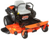
ASSEMBLY WARNING: AVOID INJURY. Read and understand the entire Safety section before proceeding. Tools Required • Adjustable wrench • 9/16" wrench • Petroleum jelly or dielectric grease. Unpack Unit Remove unit and all other components from the shipping container. Engage transmission bypass lever (see MOVING UNIT MANUALLY on page 16). Push unit from container onto a level surface. Disengage transmission bypass lever. Connect Battery See Battery Removal and Installation on page 21 and perform steps 2 and 3 in the installation section. Place Unit in Operating Position (Figure 3) NOTE: The seat is shipped with the seat positioned as far back as possible. 1. Push steering levers aside and tip seat up. 2. Adjust the seat as needed (see Adjusting Seat on page 15). 3. Remove hardware from top hole of the steering lever (Figure 3). Slide steering lever back to align slot with hole at the top of the steering pivot arm. NOTE: Do not tighten hardware before reviewing ADJUSTING STEERING LEVERS on page 23. If no adjustment is desired tighten hardware. 4. Adjust steering levers (see ADJUSTING STEERING LEVERS on page 23). 1 3 2 1. Steering Lever 2. Steering Pivot Arm 3. Steering Lever Hardware Figure 3 Place Discharge Chute in Operating Position WARNING: Do not operate mower unless the discharge chute is in the operating position. Prior to operating the unit, remove the discharge chute from the transport position and place the discharge chute in the operating position (figure 4). GB - 10
-
 1
1 -
2
-
3
-
4
-
 5
5 -
 6
6 -
 7
7 -
 8
8 -
 9
9 -
 10
10 -
 11
11 -
 12
12 -
 13
13 -
 14
14 -
 15
15 -
16
-
17
-
18
-
19
-
20
-
21
-
22
-
23
-
24
-
25
-
26
-
27
-
28
-
29
-
30
-
31
-
32
-
33
-
34
-
35
-
36
 |
 |
