Asus A-45GA Quick Reference Guide - Page 2

Package contents, Installing the power supply, Power connectors - performance

Page 2 highlights

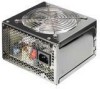
English Thank you for buying the ASUS® Power Supply! The ASUS power supply combines the latest heat management and noise-reduction technologies to ensure reliable and stable performance you can count on. The power supply features over-power protection, over-voltage protection, and short-circuit protection to prevent damage to the power supply and to your computer system. Package contents • Power supply • AC power cord • Screws (4 pcs.) • Quick reference If any of the above items is damaged or missing, contact your retailer. Installing the power supply 1. For A-series, locate the voltage selector switch at the back of the power supply. Set the power supply to the correct power voltage. • If the voltage supply in your area is 100~127V, set the switch to 115V. • If the voltage supply in your area is 200~240V, set the switch to 230V. For models with full range AC input voltage, proceed to step 2. 2. Install the power supply into the chassis and secure it with four screws. (Refer to the documentation that came with your system for specific instructions.) Power connectors The connectors from the power supply are designed to fit in only one orientation. Find the proper orientation and push down firmly until the connectors fit completely. 1. ATX motherboard connector (24-pin) This connector is for the main power connector on the motherboard. Pin Color 1 ORANGE 2 ORANGE 3 BLACK 4 RED 5 BLACK 6 RED 7 BLACK 8 GRAY 9 PURPLE 10 YELLOW 11 YELLOW 12 ORANGE Voltage Pin Color Voltage +3.3V ORANGE +3.3V +3.3V 13 BROWN +3.3VS GND +5V GND +5V GND PS +5VSB +12V1 +12V1 +3.3V 14 BLUE -12V 15 BLACK GND 16 GREEN PS-ON 17 BLACK GND 18 BLACK GND 19 BLACK GND 20 NC 21 RED +5V 22 RED +5V 23 RED +5V 24 BLACK GND 2 ASUS power supply

  • 1
  • 2
  • 3
  • 4

2
ASUS power supply
ASUS power supply
ASUS power supply
ASUS power supply
ASUS power supply
English
Thank you for buying the ASUS
®
®
®
®
®
Power Supply!
Power Supply!
Power Supply!
Power Supply!
Power Supply!
The ASUS power supply combines the latest heat management and noise-reduction
technologies to ensure reliable and stable performance you can count on. The power
supply features over-power protection, over-voltage protection, and short-circuit
protection to prevent damage to the power supply and to your computer system.
Package contents
Power supply
AC power cord
Screws (4 pcs.)
Quick reference
Installing the power supply
1.
For A-series, locate the voltage selector switch at the back of the power supply.
Set the power supply to the correct power voltage.
If the voltage supply in your area is 100~127V, set the switch to 115V.
If the voltage supply in your area is 200~240V, set the switch to 230V.
For models with full range AC input voltage, proceed to step 2.
2.
Install the power supply into the chassis and secure it with four screws.
(Refer to the documentation that came with your system for specific
instructions.)
Power connectors
1.
1.
1.
1.
1.
ATX motherboard connector
(24-pin)
(24-pin)
(24-pin)
(24-pin)
(24-pin)
This connector is for
the main power
connector on the
motherboard.
If any of the above items is damaged or missing, contact your retailer.
The connectors from the power supply are designed to fit in only one
orientation. Find the proper orientation and push down firmly until the
connectors fit completely.
Pin
Pin
Pin
Pin
Pin
Color
Color
Color
Color
Color
Voltage
Voltage
Voltage
Voltage
Voltage
Pin
Pin
Pin
Pin
Pin
Color
Color
Color
Color
Color
Voltage
Voltage
Voltage
Voltage
Voltage
1
ORANGE
+3.3V
ORANGE
+3.3V
2
ORANGE
+3.3V
13
BROWN
+3.3VS
3
BLACK
GND
14
BLUE
-12V
15
BLACK
GND
4
RED
+5V
16
GREEN
PS-ON
5
BLACK
GND
17
BLACK
GND
6
RED
+5V
18
BLACK
GND
7
BLACK
GND
19
BLACK
GND
8
GRAY
PS
20
NC
9
PURPLE
+5VSB
21
RED
+5V
10
YELLOW
+12V1
22
RED
+5V
11
YELLOW
+12V1
23
RED
+5V
12
ORANGE
+3.3V
24
BLACK
GND