Asus A55M-E A55M-E User's Manual - Page 23
Internal connectors, Video Graphics Adapter VGA port. - no video
 |
View all Asus A55M-E manuals
Add to My Manuals
Save this manual to your list of manuals |
Page 23 highlights
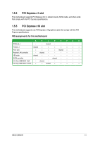
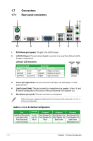
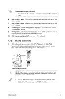
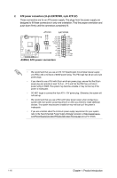
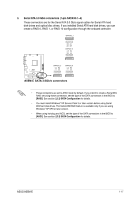
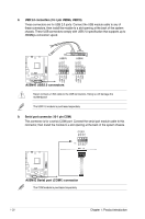
To configure an 8-channel audio output: Use a chassis with HD audio module in the front panel to support an 8-channel audio output. 6. USB 2.0 ports 1 and 2. These two 4-pin Universal Serial Bus (USB) ports are for USB 2.0/1.1 devices. 7. USB 2.0 ports 3 and 4. These two 4-pin Universal Serial Bus (USB) ports are for USB 2.0/1.1 devices. 8. Video Graphics Adapter (VGA) port. This 15-pin port is for a VGA monitor or other VGA-compatible devices. 9. DVI-D port. This port is for any DVI-D compatible device. DVI-D can't be converted to output RGB Signal to CRT and isn't compatible with DVI-I. 10. PS/2 Keyboard port (purple). This port is for a PS/2 keyboard. 1.7.2 Internal connectors 1. CPU and chassis fan connectors (4-pin CPU_FAN, and 3-pin CHA_FAN) Connect the fan cables to the fan connectors on the motherboard, ensuring that the black wire of each cable matches the ground pin of the connector. CPU_FAN CPU FAN PWM CPU FAN IN CPU FAN PWR GND A55M-E CHA_FAN Rotation +12V GND A55M-E Fan connectors DO NOT forget to connect the fan cables to the fan connectors. Insufficient air flow inside the system may damage the motherboard components. These are not jumpers! DO NOT place jumper caps on the fan connectors. • The CPU_FAN connector supports a CPU fan of maximum 2A (24 W) fan power. • Only the CPU_FAN connector support the ASUS Fan Xpert feature. ASUS A55M-E 1-15
-
 1
1 -
2
-
3
-
4
-
5
-
6
-
7
-
8
-
9
-
10
-
11
-
12
-
13
-
14
-
15
-
16
-
17
-
 18
18 -
 19
19 -
 20
20 -
 21
21 -
 22
22 -
 23
23 -
 24
24 -
 25
25 -
 26
26 -
 27
27 -
 28
28 -
29
-
30
-
31
-
32
-
33
-
34
-
35
-
36
-
37
-
38
-
39
-
40
-
41
-
42
-
43
-
44
-
45
-
46
-
47
 |
 |