Asus A58M-A BR User Guide - Page 21
Internal connectors, Audio 2.1
 |
View all Asus A58M-A BR manuals
Add to My Manuals
Save this manual to your list of manuals |
Page 21 highlights
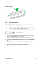
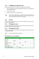
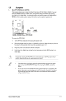
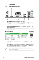
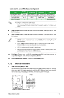
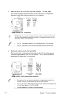
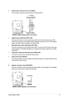
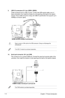
Audio 2.1, 4.1, 5.1, or 7.1-channel configuration Port Headset 2.1-channel 4.1-channel Light Blue (Rear panel) Line In Rear Speaker Out Lime (Rear panel) Line Out Front Speaker Out Pink (Rear panel) Mic In Mic In Lime (Front panel) - - 5.1-channel Rear Speaker Out Front Speaker Out Bass/Center - 7.1-channel Rear Speaker Out Front Speaker Out Bass/Center Side Speaker Out To configure a 7.1-channel audio output: Use a chassis with HD audio module in the front panel to support a 7.1-channel audio output. 8. USB 2.0 ports 1 and 2. These two 4-pin Universal Serial Bus (USB) ports are for USB 2.0/1.1 devices. 9. USB 3.0 ports 1 and 2. These two 9-pin Universal Serial Bus (USB) ports are for USB 3.0 devices. • DO NOT connect a keyboard / mouse to any USB 3.0 port when installing Windows® operating system. • Due to USB 3.0 controller limitations, USB 3.0 devices can only be used under a Windows® OS environment and after USB 3.0 driver installation. • USB 3.0 devices can only be used for data storage. • We strongly recommend that you connect USB 3.0 devices to USB 3.0 ports for faster and better performance from your USB 3.0 devices. 10. DVI-D port. This port is for any DVI-D compatible device. DVI-D can't be converted to output RGB Signal to CRT and isn't compatible with DVI-I. 11. PS/2 Keyboard port (purple). This port is for a PS/2 keyboard. 1.7.2 Internal connectors 1. TPM connector (20-1 pin TPM) This connector supports a Trusted Platform Module (TPM) system, which can securely store keys, digital certificates, passwords and data. A TPM system also helps enhance network security, protects digital identities, and ensures platform integrity. TPM SB_SUS_STAT GND +3VSB SMBSCL LAD0 +3V LAD3 PCIRST# FRAME PCICLK A58M-A/USB3 PIN 1 RESET GPIO SERIRQ SMBSDA GND LAD1 LAD2 PWROWN GND A58M-A/USB3 TPM connector ASUS A58M-A/USB3 1-13
-
 1
1 -
2
-
3
-
4
-
5
-
6
-
7
-
8
-
9
-
10
-
11
-
12
-
13
-
14
-
15
-
 16
16 -
 17
17 -
 18
18 -
 19
19 -
 20
20 -
 21
21 -
 22
22 -
 23
23 -
 24
24 -
 25
25 -
 26
26 -
27
-
28
-
29
-
30
-
31
-
32
-
33
-
34
-
35
-
36
-
37
-
38
-
39
-
40
-
41
-
42
-
43
-
44
-
45
-
46
-
47
-
48
-
49
-
50
-
51
-
52
-
53
-
54
-
55
-
56
-
57
-
58
-
59
-
60
-
61
-
62
-
63
-
64
 |
 |
