Asus A58M-F User Guide
Asus A58M-F Manual
 |
View all Asus A58M-F manuals
Add to My Manuals
Save this manual to your list of manuals |
Asus A58M-F manual content summary:
- Asus A58M-F | User Guide - Page 1
A58M-E Motherboard - Asus A58M-F | User Guide - Page 2
service will not be extended if: (1) the product is repaired, modified or altered, unless such repair, modification of alteration is authorized in writing by ASUS; or (2) the serial number of the product is defaced or missing. ASUS PROVIDES THIS MANUAL from http://support.asus.com/download problems - Asus A58M-F | User Guide - Page 3
guide...iv Package contents...vi A58M-E specifications summary vi Product introduction 1.1 Before you proceed 1-1 1.2 Motherboard overview 1-1 1.3 Accelerated Processing Unit (APU 1-3 1.4 System memory 1-6 1.5 Expansion slots 1-9 1.6 Jumpers...1-10 1.7 Connectors 1-12 1.8 Software support - Asus A58M-F | User Guide - Page 4
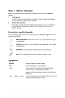
away from connectors, slots, sockets and circuitry. • Avoid problems with the product, contact a qualified service technician or your retailer. About this guide This user guide contains the information you need when installing and configuring the motherboard. How this guide is organized This guide - Asus A58M-F | User Guide - Page 5
note of the following symbols used throughout this manual. DANGER/WARNING: Information to prevent injury to yourself when trying to complete a task. CAUTION: Information to prevent damage to the components when trying to complete a task IMPORTANT: Instructions that you MUST follow to complete a task - Asus A58M-F | User Guide - Page 6
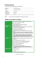
DVD Documentation ASUS A58M-E motherboard 2 x Serial ATA 3.0 Gb/s cables 1 x I/O Shield Support DVD User Guide If any of the above items is damaged or missing, contact your retailer. A58M-E specifications summary CPU Chipset Memory Graphics Expansion slots AMD® FM2+ Socket for AMD® A-Series - Asus A58M-F | User Guide - Page 7
Audio CODEC • Use a chassis with HD audio module in the front panel to support a 7.1-channel audio output. AMD® A58 FCH: - 8 x USB 2.0/1.1 ports (4 ports at the mid-board, 4 ports at the back panel) ASUS 5X Protection - ASUS motherboards safeguard your PC with 5X Protection: DIGI+VRM, DRAM Fuse, ESD - Asus A58M-F | User Guide - Page 8
connectors support additional 4 USB 2.0 ports 6 x SATA 3.0Gb/s connectors 1 x COM connector 1 x TPM header 1 x System panel connector 1 x Internal Speaker connector 1 x 4-pin CPU fan connector 1 x S/PDIF output connector 1 x 4-pin Chassis fan connector 1 x High Definition Front panel audio connector - Asus A58M-F | User Guide - Page 9
precautions before you install motherboard components or change any motherboard settings. • Unplug the power cord from the wall socket before touching any component circles to secure the motherboard to the chassis. Do not overtighten the screws! Doing so can damage the motherboard. ASUS A58M-E 1-1 - Asus A58M-F | User Guide - Page 10
+VRM CPU_FAN CHA_FAN DDR3 DIMM_A1 (64bit, 240-pin module) DDR3 DIMM_B1 (64bit, 240-pin module) SOCKET FM2+ DVI_VGA 22.6cm(8.9in) 1-2 USB1112 EATXPWR KB_USBWB LAN_USB12 2 AUDIO A58M-E 6 8111 GR PCIEX16 SATA3G_4 SATA3G_5 SATA3G_6 Super I/O PCIEX1_1 BATTERY AMD® A58 SPEAKER 7 ALC - Asus A58M-F | User Guide - Page 11
15. Front panel audio connector (10-1 pin AAFP) Page 1-12 1-15 1-3 1-14 1-6 1-18 1-16 1-17 1-19 1-11 1-10 1-14 1-16 1-19 1-18 1.3 Accelerated Processing Unit (APU) This motherboard comes with an FM2+ socket designed for AMD® A-series / Athlon™ Series graphics. A58M-E A58M-E CPU socket FM2+ Ensure - Asus A58M-F | User Guide - Page 12
1.3.1 Installing the APU 1 2 3 4 1.3.2 APU heatsink and fan assembly installation Apply the Thermal Interface Material to the APU heatsink and APU before you install the heatsink and fan if necessary. 1-4 Chapter 1: Product introduction - Asus A58M-F | User Guide - Page 13
To install the APU heatsink and fan assembly 1 2 3 4 5 To uninstall the APU heatsink and fan assembly 1 2 3 ASUS A58M-E 1-5 - Asus A58M-F | User Guide - Page 14
1.4 System memory 1.4.1 Overview The motherboard comes with two Double Data Rate 3 (DDR3) Dual Inline Memory Modules (DIMM) sockets. A DDR3 module has the same physical dimensions as a DDR2 DIMM but is notched differently to prevent installation on a DDR2 DIMM socket. DDR3 modules are developed for - Asus A58M-F | User Guide - Page 15
DDR3 DIMMs into the DIMM sockets motherboard manual memory frequency adjustment. • For system stability, use a more efficient memory cooling system to support a full memory load (2 DIMMs) or overclocking condition. • Refer to www.asus.com for the latest Memory QVL (Qualified Vendors List). ASUS A58M - Asus A58M-F | User Guide - Page 16
1.4.3 1 Installing a DIMM 2 3 To remove a DIMM B A 1-8 A Chapter 1: Product introduction - Asus A58M-F | User Guide - Page 17
hardware settings for the card. 2. Remove the system unit cover (if your motherboard is already installed in a chassis). 3. Remove the bracket opposite the slot that PCI slot supports cards such as a LAN card, SCSI card, USB card, and other cards that comply with PCI specifications. ASUS A58M-E 1-9 - Asus A58M-F | User Guide - Page 18
motherboard supports PCI Express 2.0 x1 network cards, SCSI cards, and other cards that comply with the PCI Express specifications. 1.5.5 PCI Express x16 slot This motherboard supports passwords. A58M-E CLRTC 12 23 Normal (Default) A58M-E Clear RTC RAM Clear RTC 1-10 Chapter - Asus A58M-F | User Guide - Page 19
(no power to CPU, DRAM in slow refresh, power supply in reduced power mode). A58M-E USBPWF 12 23 +5V +5VSB (Default) A58M-E USB device wake up • The USB device wake-up feature requires a power supply that capability (+5VSB) whether under normal condition or in sleep mode. ASUS A58M-E 1-11 - Asus A58M-F | User Guide - Page 20
at least 1A on the +5VSB lead, and a corresponding setting in the BIOS. KB_USBPWB 12 23 A58M-E +5V +5VSB (Default) A58M-E Keyboard and USB device wake up 1.7 1.7.1 1 Connectors Rear panel connectors 2 3 45 10 9 8 7 6 1. PS/2 Mouse port (green). This port is for a PS/2 mouse. 2. Video - Asus A58M-F | User Guide - Page 21
Side Speaker Out To configure a 7.1-channel audio output: Use a chassis with HD audio module in the front panel to support a 7.1-channel audio output. 7. USB 2.0 ports 1 and 2. These two 4-pin Universal Serial Bus . PS/2 Keyboard port (purple). This port is for a PS/2 keyboard. ASUS A58M-E 1-13 - Asus A58M-F | User Guide - Page 22
inside the system may damage the motherboard components. These are not jumpers! DO NOT place jumper caps on the fan connectors. • The CPU_FAN connector supports a CPU fan of maximum 2A (24 W) fan power. • The CPU_FAN and CHA_FAN connectors support the ASUS Fan Xpert feature. 2. TPM connector (20 - Asus A58M-F | User Guide - Page 23
push down firmly until the connectors completely fit. ATX12V EATXPWR +12V DC +12V DC A58M-E GND GND +3 Volts +12 Volts +12 Volts +5V Standby Power OK PIN 1 Wattage Calculator at http://support.asus. com/PowerSupplyCalculator/PSCalculator.aspx?SLanguage=en-us for details. ASUS A58M-E 1-15 - Asus A58M-F | User Guide - Page 24
RSATA_RXN2 RSATA_RXP2 GND GND RSATA_TXP3 RSATA_TXN3 GND RSATA_RXN3 RSATA_RXP3 GND A58M-E SATA 3.0Gb/s connectors • These connectors are set SATA connectors in the BIOS to [RAID]. • You must install Windows® XP Service Pack 3 or later version before using Serial ATA hard disk drives. The Serial - Asus A58M-F | User Guide - Page 25
PANEL) This connector supports several chassis-mounted functions. F_PANEL +PWR LED PWR BTN PWR_LED+ PWR_LEDPWR GND HDD_LED+ HDD_LED- Ground HWRST# (NC) A58M-E PIN 1 +HDD_LED RESET A58M-E System panel reset button for system reboot without turning off the system power. ASUS A58M-E 1-17 - Asus A58M-F | User Guide - Page 26
PORT2 R SENSE_SEND PORT2 L A58M-E HD-audio-compliant pin definition A58M-E Front panel audio connector Legacy ACʼ97 compliant definition • We recommend that you connect a high-definition front panel audio module to this connector to avail of the motherboard high-definition audio capability. • If - Asus A58M-F | User Guide - Page 27
supports up to 480Mbps connection speed. USB56 USB34 USB+5V USB_P5USB_P5+ GND NC USB+5V USB_P3USB_P3+ GND NC A58M-E PIN 1 PIN 1 USB+5V USB_P6USB_P6+ GND USB+5V USB_P4USB_P4+ GND A58M-E USB2.0 connectors Never connect a 1394 cable to the USB connectors. Doing so will damage the motherboard - Asus A58M-F | User Guide - Page 28
screen which contains the unique features of ASUS motherboard. Click Drivers, Utilities, Make Disk, Manual, Contact and Specials tabs to display their respective menus. The following screen is for reference only. Click an icon to display Support DVD/motherboard information Click an item to install - Asus A58M-F | User Guide - Page 29
:0205 Release Date: 02/12/2014 C:\Users\test\Downloads\A58M-E-ASUS-02... Click to find and select the BIOS from file Click to select a boot logo Click to update the BIOS EZ Update requires an Internet connection either through a network or an ISP (Internet Service Provider). ASUS A58M-E 2-1 - Asus A58M-F | User Guide - Page 30
download the latest BIOS file from the ASUS website at www.asus.com. To update the BIOS using EZ motherboard support DVD or a USB flash drive that contains the updated BIOS file. • Before using this utility, rename the BIOS file in the removable device into A58ME.CAP. • The BIOS file in the support - Asus A58M-F | User Guide - Page 31
://support.asus.com and save them on the USB flash drive. NTFS is not supported under DOS environment. Do not save the BIOS file and BIOS Updater to a hard disk drive or USB flash drive in NTFS format. 3. Turn off the computer and disconnect all SATA hard disk drives (optional). ASUS A58M-E 2-3 - Asus A58M-F | User Guide - Page 32
Updater to your computer's USB port. 2. Boot your computer. When the ASUS Logo appears, press to show the BIOS Boot Device Select Menu. .30 Current ROM BOARD: A58M-E VER: 0205 DATE: 02/12/2014 Update ROM BOARD: Unknown VER: Unknown DATE: Unknown PATH: A:\ A: A58ME.CAP 8390656 2014-02-12 - Asus A58M-F | User Guide - Page 33
to update the BIOS or configure its parameters. The BIOS screens include navigation keys and brief online help to guide you in using the BIOS Setup program. Entering BIOS Setup at startup To enter BIOS Setup at startup: • you failed to enter BIOS Setup using the first two options. ASUS A58M-E 2-5 - Asus A58M-F | User Guide - Page 34
purposes only, and may not exactly match what you see on your screen. • Visit the ASUS website at www.asus.com to download the latest BIOS file for this motherboard. • Ensure that a USB mouse is connected to your motherboard if you want to use the mouse to control the BIOS setup program. • If the - Asus A58M-F | User Guide - Page 35
on the devices you installed to the system. • The Boot Menu(F8) button is available only when the boot device is installed to the system. ASUS A58M-E 2-7 - Asus A58M-F | User Guide - Page 36
an example of the Advanced Mode. Refer to the following sections for the detailed configurations. To access the EZ Mode, click Exit, then select ASUS EZ Mode or press F7. Back button Menu items Menu bar Configuration fields General help Submenu item Pop-up window Navigation keys Menu bar The - Asus A58M-F | User Guide - Page 37
: • Items with submenu options • User-configurable items such as language and boot device order • Configuration items such as Memory SPD Information, system time and date ASUS A58M-E 2-9 - Asus A58M-F | User Guide - Page 38
2.4 Main menu The Main menu screen appears when you enter the Advanced Mode of the BIOS Setup program. The Main menu provides you an overview of the basic system information, and allows you to set the system date, time, language, and security settings. • If you have forgotten your BIOS password, - Asus A58M-F | User Guide - Page 39
values can cause the system to malfunction. The configuration options for this section vary depending on the CPU and DIMM model you installed on the motherboard. Scroll down to display the other items. ASUS A58M-E 2-11 - Asus A58M-F | User Guide - Page 40
2.6 Advanced menu The Advanced menu items allow you to change the settings for the CPU and other system devices. Be cautious when changing the settings of the Advanced menu items. Incorrect field values can cause the system to malfunction. 2.7 Monitor menu The Monitor menu displays the system - Asus A58M-F | User Guide - Page 41
2.8 Boot menu The Boot menu items allow you to change the system boot options. Scroll down to display the other items. ASUS A58M-E 2-13 - Asus A58M-F | User Guide - Page 42
2.9 Tools menu The Tools menu items allow you to configure options for special functions. Select an item then press to display the submenu. 2.10 Exit menu The Exit menu items allow you to load the optimal default values for the BIOS items, and save or discard your changes to the BIOS items. - Asus A58M-F | User Guide - Page 43
radiate radio frequency energy and, if not installed and used in accordance with manufacturer's instructions, may cause harmful interference to radio communications. However, there is no guarantee that for compliance could void the user's authority to operate this equipment. ASUS A58M-E A-1 - Asus A58M-F | User Guide - Page 44
IC: Canadian Compliance Statement Complies with the Canadian ICES-003 Class B specifications. This device complies with RSS 210 of Industry Canada. This Class B device meets all the requirements of the Canadian interference-causing equipment regulations. This device complies with Industry Canada - Asus A58M-F | User Guide - Page 45
at ASUS REACH website at http://csr.asus.com/english/REACH.htm. DO NOT throw the motherboard placed in municipal waste. ASUS Recycling/Takeback Services ASUS recycling and takeback programs come asus.com/english/Takeback.htm for detailed recycling information in different regions. ASUS A58M-E A-3 - Asus A58M-F | User Guide - Page 46
+1-510-739-3777 Fax +1-510-608-4555 Web site http://usa.asus.com Technical Support Support fax General support Online support +1-812-284-0883 +1-812-282-2787 http://support.asus.com/techserv/techserv.aspx ASUS COMPUTER GmbH (Germany and Austria) Address Harkort Str. 21-23, D-40880 - Asus A58M-F | User Guide - Page 47
A-5 ASUS A58M-E DECLARATION OF CONFORMITY Per FCC Part 2 Section 2. 1077(a) Responsible Party Name: Asus Computer International Address: 800 Corporate Way, Fremont, CA 94539. Phone/Fax No: (510)739-3777/(510)608-4555 hereby declares that the product Product Name : Motherboard Model Number : A58M
-
 1
1 -
 2
2 -
 3
3 -
 4
4 -
 5
5 -
 6
6 -
 7
7 -
8
-
9
-
10
-
11
-
12
-
13
-
14
-
15
-
16
-
17
-
18
-
19
-
20
-
21
-
22
-
23
-
24
-
25
-
26
-
27
-
28
-
29
-
30
-
31
-
32
-
33
-
34
-
35
-
36
-
37
-
38
-
39
-
40
-
41
-
42
-
43
-
44
-
45
-
46
-
47
 |
 |

Motherboard
A58M-E