Asus A58M-F User Guide - Page 11
Accelerated Processing Unit (APU), ASUS A58M-E - motherboard k fm2
 |
View all Asus A58M-F manuals
Add to My Manuals
Save this manual to your list of manuals |
Page 11 highlights
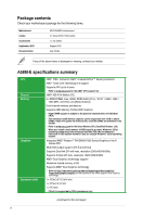
Connectors/Jumpers/Slots/LED 1. Keyboard and USB device wake up (3-pin KB_USBPWB) 2. ATX power connectors (24-pin EATXPWR, 4-pin ATX12V) 3. AMD FM2+ socket 4. CPU and chassis fan connectors (4-pin CPU_FAN and 4-pin CHA_FAN) 5. DDR3 DIMM slots 6. Speaker connector (4-pin SPEAKER) 7. SATA 3.0Gb/s connectors (7-pin SATA3G_1~6) 8. System panel connector (10-1 pin F_PANEL) 9. USB 2.0 connectors (10-1 pin USB34, USB56) 10. USB device wake-up (3-pin USBPWF) 11. Clear RTC RAM (3-pin CLRTC) 12. TPM connector (20-1 pin TPM) 13. Digital audio connector (4-1 pin SPDIF_OUT) 14. Serial port connector (10-1 pin COM) 15. Front panel audio connector (10-1 pin AAFP) Page 1-12 1-15 1-3 1-14 1-6 1-18 1-16 1-17 1-19 1-11 1-10 1-14 1-16 1-19 1-18 1.3 Accelerated Processing Unit (APU) This motherboard comes with an FM2+ socket designed for AMD® A-series / Athlon™ Series graphics. A58M-E A58M-E CPU socket FM2+ Ensure that you use an APU designed for the FM2+ socket. The APU fits in only one correct orientation. DO NOT force the APU into the socket to prevent bending the pins and damaging the APU! ASUS A58M-E 1-3
-
 1
1 -
2
-
3
-
4
-
5
-
 6
6 -
 7
7 -
 8
8 -
 9
9 -
 10
10 -
 11
11 -
 12
12 -
 13
13 -
 14
14 -
 15
15 -
 16
16 -
17
-
18
-
19
-
20
-
21
-
22
-
23
-
24
-
25
-
26
-
27
-
28
-
29
-
30
-
31
-
32
-
33
-
34
-
35
-
36
-
37
-
38
-
39
-
40
-
41
-
42
-
43
-
44
-
45
-
46
-
47
 |
 |
