Asus A7V266-E AA A7V266-E User Manual - Page 23
ASUS A7V266-E User's Manual, USB Device Wake-up, USB01_PWR/USB23_PWR/USB45_PWR, NOTES, IDE Channel
 |
View all Asus A7V266-E AA manuals
Add to My Manuals
Save this manual to your list of manuals |
Page 23 highlights
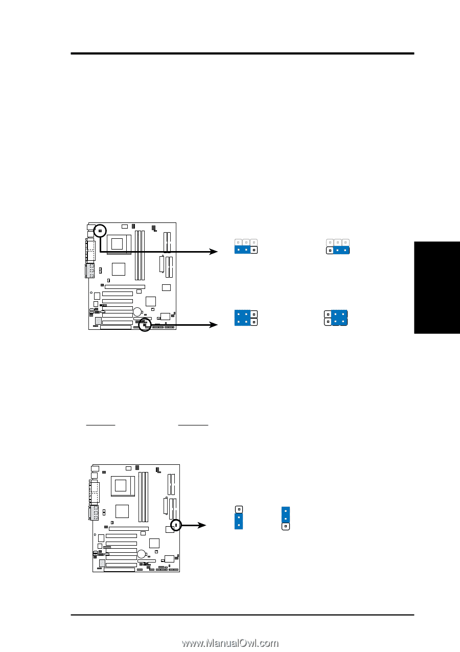
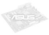
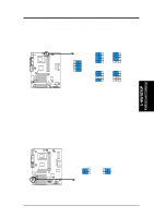
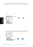
3. HARDWARE SETUP 10) USB Device Wake-up (USB01_PWR/USB23_PWR/USB45_PWR) Set these jumpers to +5V to allow wake up from the S1 sleep state (CPU stopped; RAM refreshed; system running in low power mode) using the connected USB devices. Set to +5VSB to allow wake up from S3 sleep state (no power to CPU; RAM in slow refresh; power supply in reduced power mode). The default setting for the three jumpers is 1-2 to select +5V (because not all computers have the appropriate power supply). NOTES: 1. This feature requires an ATX power supply that can supply at least 2A on the +5VSB lead when these jumpers are set to +5VSB. Otherwise, the system does not power up. 2. The total current consumed must NOT exceed the power supply capability (+5VSB) whether under normal working conditions or in sleep mode. 12 23 USB01_PWR +5V +5VSB 3. H/W SETUP Motherboard Settings 01 01 01 01 01 01 A7V266-E A7V266-E USB Device Wake Up 12 23 USB23_PWR USB45_PWR +5V +5VSB 11) IDE Channel Setting for ATA100 or RAID 0/1 (JP2601) These jumpers enable the ATA100 IDE Controller, or the IDE RAID controller function. The default setting enables ATA100. Setting JP2601 Enable ATA100 [1-2] (default) Enable RAID 0/1 [2-3] A7V266-E JP2601 2 1 ATA100 (Default) 3 2 RAID0/1 A7V266-E ATA100/RAIDO Selection ASUS A7V266-E User's Manual 23
-
 1
1 -
2
-
3
-
4
-
5
-
6
-
7
-
8
-
9
-
10
-
11
-
12
-
13
-
14
-
15
-
16
-
17
-
 18
18 -
 19
19 -
 20
20 -
 21
21 -
 22
22 -
 23
23 -
 24
24 -
 25
25 -
 26
26 -
 27
27 -
 28
28 -
29
-
30
-
31
-
32
-
33
-
34
-
35
-
36
-
37
-
38
-
39
-
40
-
41
-
42
-
43
-
44
-
45
-
46
-
47
-
48
-
49
-
50
-
51
-
52
-
53
-
54
-
55
-
56
-
57
-
58
-
59
-
60
-
61
-
62
-
63
-
64
-
65
-
66
-
67
-
68
-
69
-
70
-
71
-
72
-
73
-
74
-
75
-
76
-
77
-
78
-
79
-
80
-
81
-
82
-
83
-
84
-
85
-
86
-
87
-
88
-
89
-
90
-
91
-
92
-
93
-
94
-
95
-
96
-
97
-
98
-
99
-
100
-
101
-
102
-
103
-
104
-
105
-
106
-
107
-
108
 |
 |