Asus A7V8X Motherboard DIY Troubleshooting Guide - Page 5
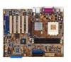
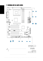
Motherboard-Layout
 |
View all Asus A7V8X manuals
Add to My Manuals
Save this manual to your list of manuals |
Page 5 highlights
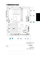
Deutsch 1. Motherboard-Layout PS/2KBMS T: Mouse B: Keyboard USB1.1 T: USB0 B: USB1 OVER_VOLT1 KBPWR1 USBPWR_12 USBPWR_34 COM1 CPU_FAN1 OVER_VOLT1 12 23 OVERVOLT ENABLE OVERVOLT DISABLE (Default) ATX Power Connector Socket 462 DDR DIMM1 (64/72 bit, 184-pin module) DDR DIMM2 (64/72 bit, 184-pin module) DDR DIMM3 (64/72 bit, 184-pin module) PARALLEL PORT KBPWR1 12 23 COM2 USB2.0 Top: T: USB1 RJ-45 B: USB2 Top:Line In Center:Line Out Below:Mic In VIA KT400 Chipset PWR_FAN1 AUX1 CD1 Accelerated Graphics Port (AGP Pro) 01 23 45 FP_AUDIO1 GBLAN or LAN Chip Audio Codec MODEM1 SPEECH Controller SPDIF1 VIA 1394 Controller PCI1 AGP_WARN1 PCI2 VIA VT8235 Chipset SMB_CON1 TRPWR1 PCI3 ® A7V8X PCI4 CR2032 3V Lithium Cell CMOS Power CLRTC1 ASUS ASIC with Hardware Monitor USBPWR_56 Super I/O PROMISE PDC20376 SerialATA Controller PCI5 PCI6 USB56 SB_PWR1 SMARTCARD1 SEC_SATA1 4Mbit Firmware Hub PRI_SATA1 CHASSIS1 CHA_FAN1 IDELED1 IEEE1394_1 IEEE1394_2 GAME1 WPCI_USB1 IR_CON1 AFPANEL1 PANEL1 PRI_ IDE1 SEC_ IDE1 FLOPPY1 PRI_RAID1 +5V (Default) +5VSB USBPWR_12 USBPWR_34 12 23 +5V (Default) +5VSB WPCI_USB1 6 5 4 34 3 2 1 Wireless PCI_USB Original PCI reserved pin (Default) USBPWR_56 12 23 +5V (Default) +5VSB CLRTC1 12 23 Clear CMOS Normal (Default) PANEL1 TastaturLock Strom-LED Lautsprecheranschluss PLED+ PLEDKeylock Ground +5V Ground Ground Speaker Anmerkung: Die Audio-, SATA-, Gigabit LAN-, LAN- und 1394-Funktionen sind optionale Ausstattungen und sind deshalb im obigen Motherboard-Layout dargestellt. ExtSMI# Ground PWR Ground Reset Ground Reset-Schalter SMI-Leiter ATX-Stromschalter * Benötigt ATX-Stromversorgung. ASUS A7V8X-Motherboard 5
-
 1
1 -
 2
2 -
 3
3 -
 4
4 -
 5
5 -
 6
6 -
 7
7 -
 8
8 -
 9
9 -
 10
10 -
 11
11 -
12
-
13
-
14
-
15
-
16
 |
 |
