Asus A8V-MX A8V-MX User''s Manual for English Edition - Page 32

Connectors

Page 32 highlights

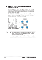
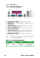
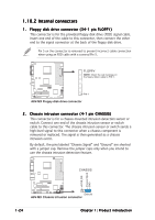
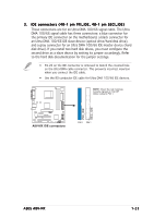
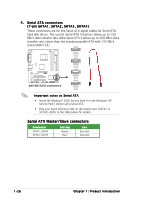
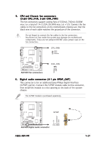
1.10 Connectors 1.10.1 Rear panel connectors 1 2 3 4 5 6 11 10 9 8 7 1 . P S / 2 m o u s e p o r t ( g r e e n ) . This port is for a PS/2 mouse. 2 . P a r a l l e l p o r t . This 25-pin port connects a parallel printer, a scanner, or other devices. 3 . L A N ( R J - 4 5 ) p o r t . This port allows connection to a Local Area Network (LAN) through a network hub. 4 . L i n e I n p o r t ( l i g h t b l u e ) . This port connects a tape, CD, DVD player, or other audio sources. 5 . L i n e O u t p o r t ( g r e e n ) . This port connects a headphone or a speaker. In 4-channel/ 6-channel configuration, the function of this port becomes Front Speaker Out. 6 . M i c r o p h o n e p o r t ( p i n k ) . This port connects a microphone. Refer to the audio configuration table for the function of the audio ports in 2, 4, or 6,-channel configuration. Audio 2, 4, or 6-channel configuration Port Light Blue Green Pink Headset 2-channel Line In Line Out Mic In 4-channel Rear Speaker Out Front Speaker Out Mic In 6-channel Rear Speaker Out Front Speaker Out Center/Subwoofer Speaker Out 1-22 Chapter 1: Product introduction

  • 1
  • 2
  • 3
  • 4
  • 5
  • 6
  • 7
  • 8
  • 9
  • 10
  • 11
  • 12
  • 13
  • 14
  • 15
  • 16
  • 17
  • 18
  • 19
  • 20
  • 21
  • 22
  • 23
  • 24
  • 25
  • 26
  • 27
  • 28
  • 29
  • 30
  • 31
  • 32
  • 33
  • 34
  • 35
  • 36
  • 37
  • 38
  • 39
  • 40
  • 41
  • 42
  • 43
  • 44
  • 45
  • 46
  • 47
  • 48
  • 49
  • 50
  • 51
  • 52
  • 53
  • 54
  • 55
  • 56
  • 57
  • 58
  • 59
  • 60
  • 61
  • 62
  • 63
  • 64
  • 65
  • 66
  • 67
  • 68
  • 69
  • 70
  • 71
  • 72
  • 73
  • 74
  • 75
  • 76
  • 77
  • 78
  • 79
  • 80
  • 81
  • 82
  • 83
  • 84
  • 85
  • 86
  • 87
  • 88
  • 89
  • 90

1-22
1-22
1-22
1-22
1-22
Chapter 1: Product introduction
Audio 2, 4, or 6-channel configuration
Port
Port
Port
Port
Port
Headset
Headset
Headset
Headset
Headset
4-channel
4-channel
4-channel
4-channel
4-channel
6-channel
6-channel
6-channel
6-channel
6-channel
2-channel
2-channel
2-channel
2-channel
2-channel
Light Blue
Line In
Rear Speaker Out
Rear Speaker Out
Green
Line Out
Front Speaker Out
Front Speaker Out
Pink
Mic In
Mic In
Center/Subwoofer Speaker Out
Refer to the audio configuration table for the function of the audio ports
in 2, 4, or 6,-channel configuration.
1.10
Connectors
1.10.1
1.10.1
1.10.1
1.10.1
1.10.1 Rear panel connectors
Rear panel connectors
1.
1.
1.
1.
1.
PS/2 mouse port (green).
PS/2 mouse port (green). This port is for a PS/2 mouse.
2.
2.
2.
2.
2.
Parallel port.
Parallel port.
Parallel port.
Parallel port.
Parallel port. This 25-pin port connects a parallel printer, a scanner,
or other devices.
3.
3.
3.
3.
3.
LAN (RJ-45) port.
LAN (RJ-45) port.
LAN (RJ-45) port.
LAN (RJ-45) port.
LAN (RJ-45) port. This port allows connection to a Local Area
Network (LAN) through a network hub.
4.
4.
4.
4.
4.
Line In port (light blue).
Line In port (light blue). This port connects a tape, CD, DVD
player, or other audio sources.
5.
5.
5.
5.
5.
Line Out port (green).
Line Out port (green). This port connects a headphone or a
speaker. In 4-channel/ 6-channel configuration, the function of this
port becomes Front Speaker Out.
6.
6.
6.
6.
6.
Microphone port (pink).
Microphone port (pink). This port connects a microphone.
1
11
7
2
3
10
4
5
6
9
8