Asus AP1700 User Manual - Page 33
User's Manual
 |
View all Asus AP1700 manuals
Add to My Manuals
Save this manual to your list of manuals |
Page 33 highlights
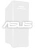
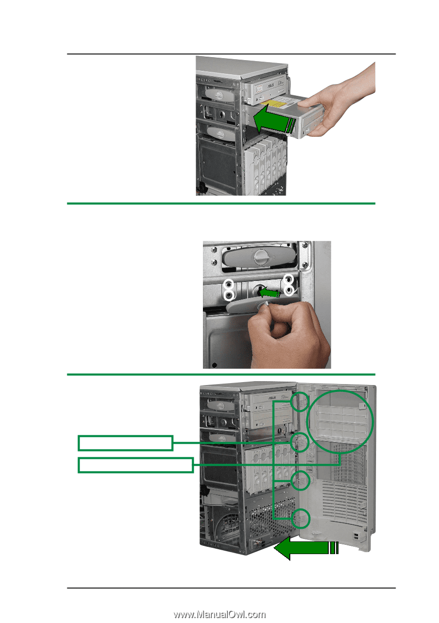
4. Carefully insert device (like an optical drive) into the selected bay. 5. Align the device screw holes with the bay slot and affix device by fastening screwless fixed device bay lock. 5.a To fasten the lock, rotate the circular knob clockwise, setting the knob guide to point to the right. 6. Remove the appropriate plastic bay cover on the front panel. Front Panel door hinges Front Panel plastic bay cover 7. Fasten the four (4) front panel hinges to the slotted chassis holes then close the front panel cover. User's Manual 2-15
-
 1
1 -
2
-
3
-
4
-
5
-
6
-
7
-
8
-
9
-
10
-
11
-
12
-
13
-
14
-
15
-
16
-
17
-
18
-
19
-
20
-
21
-
22
-
23
-
24
-
25
-
26
-
27
-
 28
28 -
 29
29 -
 30
30 -
 31
31 -
 32
32 -
 33
33 -
 34
34 -
 35
35 -
 36
36 -
 37
37 -
 38
38 -
39
-
40
-
41
-
42
-
43
-
44
-
45
-
46
-
47
-
48
-
49
-
50
-
51
-
52
-
53
-
54
 |
 |
User’s Manual
2-15
4.
Carefully insert device (like
an optical drive) into the
selected bay.
5.
Align the device screw holes with the bay slot and affix device by
fastening screwless fixed device bay lock.
5.a To fasten the lock,
rotate the circular
knob clockwise,
setting the knob
guide to point to the
right.
6.
Remove the appropriate
plastic bay cover on the
front panel.
7.
Fasten the four (4) front
panel hinges to the slotted
chassis holes then close
the front panel cover.
Front Panel plastic bay cover
Front Panel door hinges