Asus B150M-K B150M-K Users manual English - Page 12
IRQ assignments for this motherboard, Digital audio connector 4-1 pin SPDIF_OUT
 |
View all Asus B150M-K manuals
Add to My Manuals
Save this manual to your list of manuals |
Page 12 highlights
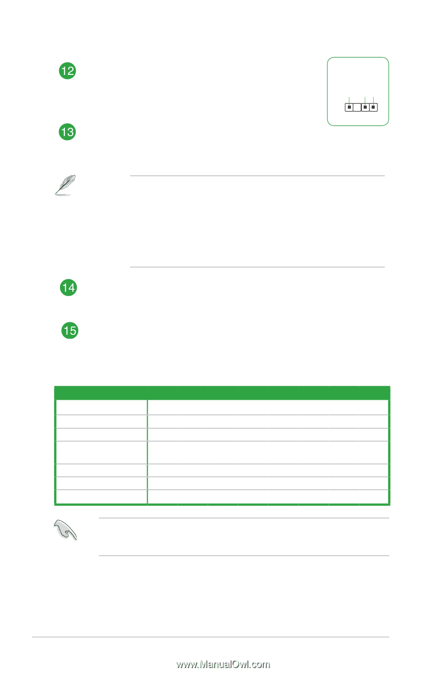
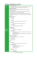
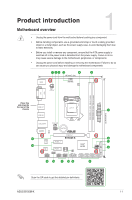
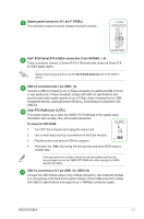
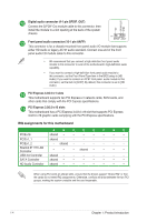
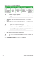
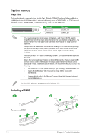
+5V SPDIFOUT GND Digital audio connector (4-1 pin SPDIF_OUT) Connect the S/PDIF Out module cable to this connector, then install the module to a slot opening at the back of the system chassis. Front panel audio connector (10-1 pin AAFP) PIN 1 SPDIF_OUT This connector is for a chassis-mounted front panel audio I/O module that supports either HD Audio or legacy AC`97 audio standard. Connect one end of the front panel audio I/O module cable to this connector. • We recommend that you connect a high-definition front panel audio module to this connector to avail of the motherboard's high-definition audio capability. • If you want to connect a high-definition front panel audio module to this connector, set the Front Panel Type item in the BIOS setup to [HD Audio]. If you want to connect an AC'97 front panel audio module to this connector, set the item to [AC97]. By default, this connector is set to [HD Audio]. PCI Express 3.0/2.0 x1 slots This motherboard supports two PCI Express x1 network cards, SCSI cards, and other cards that comply with the PCI Express specifications. PCI Express 3.0/2.0 x16 slots This motherboard has a PCI Express 3.0/2.0 x16 slot that supports PCI Express 3.0/2.0 x16 graphic cards complying with the PCI Express specifications. IRQ assignments for this motherboard A B C D E F G H PCIEx16 shared - - - - - - - PCIEx1_1 shared - - - - - - - PCIEx1_2 - shared - - - - - - Realtek 8111H LAN Controller - - - shared - - - - USB 3.0 Controller shared - - - - - - - SATA Controller shared - - - - - - - HD Audio Controller shared - - - - - - - When using PCI cards on shared slots, ensure that the drivers support "Share IRQ" or that the cards do not need IRQ assignments. Otherwise, conflicts will arise between the two PCI groups, making the system unstable and the card inoperable. 1-4 Chapter 1: Product introduction
-
 1
1 -
2
-
3
-
4
-
5
-
6
-
 7
7 -
 8
8 -
 9
9 -
 10
10 -
 11
11 -
 12
12 -
 13
13 -
 14
14 -
 15
15 -
 16
16 -
 17
17 -
18
-
19
-
20
-
21
-
22
-
23
-
24
-
25
 |
 |