Asus BM6630 User Manual - Page 16
Rear Speaker Out port black, Line In port light blue.
 |
View all Asus BM6630 manuals
Add to My Manuals
Save this manual to your list of manuals |
Page 16 highlights
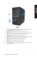
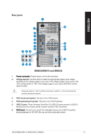
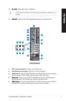
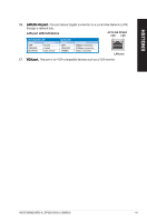
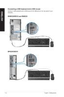
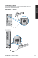
ENGLISH • DO NOT connect a keyboard / mouse to any USB 3.0 port when installing Windows® operating system. • Due to USB 3.0 controller limitation, USB 3.0 devices can only be used under Windows® OS environment and after the USB 3.0 driver installation. • USB 3.0 devices can only be used as data storage only. • We strongly recommend that you connect USB 3.0 devices to USB 3.0 ports for faster and better performance for your USB 3.0 devices. 6. ���S��id�e��S�p�e�a�k��e�r�O�u��t �p�o�r�t�(�g�r�a�y�). This port connects the side speaker in an 8-channel audio configuration. 7. Rear Speaker Out port (black). This port connects the rear speakers in a 4-channel, 6-channel, or 8-channel audio configuration. 8. ���C��e�n�t�e�r�/�S�u�b��w�o�o�f�e�r�p��o�r�t �(o��ra�n��g�e�). This port connects the center/subwoofer speakers. 9. ���M��ic�r�o�p�h��o�n�e��p�o�r�t �(p��in�k�)�. This port connects to a microphone. 10. ��L��in��e�O��u�t��p�o�r�t�(�l�im��e�)�. This port connects to a headphone or speaker. In a 4, 6, or 8-channel configuration, the function of this port becomes Front Speaker Out. 11. ���L�i�n�e��I�n��p�o�r�t�(�l�ig��h�t��b�l�u�e�)�. This port connects to a tape, CD, DVD player, or other audio sources. Refer to the audio configuration table below for the function of the audio ports in a 2, 4, or 6-channel configuration. Audio 2, 4, or 6-channel configuration Port Light Blue Lime Pink Orange Black Gray Headset 2-channel Line In Line Out Mic In - - - 4-channel Line In Front Speaker Out Mic In - Rear Speaker Out - 6-channel Line In Front Speaker Out Mic In Center/Subwoofer Rear Speaker Out - 12. ��E��x�p�a�n�s�i�o�n��s�lo��t �b�r�a�c�k�e�t�s�. Remove the expansion slot bracket when installing an expansion card. 13. Voltage selector. Use this switch to select the appropriate system input voltage according to the voltage supply in your area. If the voltage supply in your area is 100127V, set the switch to 115V. If the voltage supply in your area is 200-240V, set the switch to 230V.� DO NOT block the air vents on the chassis. Always provide proper ventilation for your computer. 14. Air vents. These vents allow air ventilation. 15. Power connector. Plug the power cord to this connector. 1-8 Chapter 1: Getting started
-
 1
1 -
2
-
3
-
4
-
5
-
6
-
7
-
8
-
9
-
10
-
 11
11 -
 12
12 -
 13
13 -
 14
14 -
 15
15 -
 16
16 -
 17
17 -
 18
18 -
 19
19 -
 20
20 -
 21
21 -
22
-
23
-
24
-
25
-
26
-
27
-
28
-
29
-
30
-
31
-
32
-
33
-
34
-
35
-
36
-
37
-
38
-
39
-
40
-
41
-
42
-
43
-
44
-
45
-
46
-
47
-
48
-
49
-
50
-
51
-
52
-
53
-
54
-
55
-
56
-
57
-
58
-
59
-
60
-
61
-
62
 |
 |