Asus CM6731 User Manual - Page 13
´oltage selector switch., Power connector., Air vents., USB 2.0 ports., D´I-D port., ´GA port.
 |
View all Asus CM6731 manuals
Add to My Manuals
Save this manual to your list of manuals |
Page 13 highlights
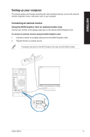
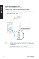
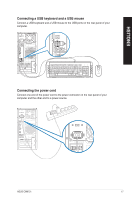
ENGLISH 1. � V�o��lt�a�g��e��s�e�l�e�c�t�o�r��s�w��i�tc��h�. Switch to select the appropriate system input voltage. 2. ���P�o�w��e�r�c�o�n�n��e�c�to�r�. Plug the power cord to this connector. 3. ���A�i�r�v�e�n�t�s�. These vents allow air ventilation. DO NOT block the air vents on the chassis. Always provide proper ventilation for your computer. 4. ���P�S��/2��K�e�y�b�o�a�r�d��/ �M�o�u�s�e��C�o�m��b�o��p�o�r�t �(�p�u�r�p�l�e�/�g�r�e�e�n�)�. This port is for a PS/2 keyboard or mouse. 5. ���U�S��B�2�.�0�p��o�rt�s�. These Universal Serial Bus 2.0 (USB 2.0) ports connect to USB 2.0 devices such as a mouse, printer, scanner, camera, PDA, and others. 6. ��DV�I�-�D��p��o�r�t�. This port is for any DVI-D compatible device and is HDCP compliant allowing playback of HD DVD, Blu-ray, and other protected content. 7. � V�G��A��p�o�r�t�. This port is for VGA-compatible devices such as a VGA monitor. 8. ���U�S��B�2�.�0�p��o�rt�s�. These Universal Serial Bus 2.0 (USB 2.0) ports connect to USB 2.0 devices such as a mouse, printer, scanner, camera, PDA, and others. 9. ��L�A�N� (�R�J�-�4�5�)�� p��o�r�t�. This port allows Gigabit connection to a Local Area Network (LAN) through a network hub. LAN port LED indications Activity/Link LED Status Description OFF No link ORANGE Linked BLINKING Data activity Speed LED Status OFF ORANGE GREEN Description 10Mbps connection 100Mbps connection 1Gbps connection ACT/LINK SPEED LED LED LAN port 10. Line In port (light blue). This port connects the tape, CD, DVD player, or other audio sources. 11. Line Out port (lime). This port connects to a headphone or a speaker. In 4-channel, 6-channel, and 8-channel configurations, the function of this port becomes Front Speaker Out. 12. Microphone port (pink). This port connects a microphone. Refer to the audio configuration table on the next page for the function of the audio ports in the 2, 4, 6, or 8-channel configuration. ASUS CM6731 13
-
 1
1 -
2
-
3
-
4
-
5
-
6
-
7
-
 8
8 -
 9
9 -
 10
10 -
 11
11 -
 12
12 -
 13
13 -
 14
14 -
 15
15 -
 16
16 -
 17
17 -
 18
18 -
19
-
20
-
21
-
22
-
23
-
24
-
25
-
26
-
27
-
28
-
29
-
30
-
31
-
32
-
33
-
34
-
35
-
36
-
37
-
38
-
39
-
40
-
41
-
42
-
43
-
44
-
45
-
46
-
47
-
48
-
49
-
50
-
51
-
52
-
53
-
54
-
55
-
56
-
57
-
58
-
59
-
60
-
61
-
62
-
63
-
64
-
65
-
66
 |
 |
