Asus CUBX CUBX User Manual - Page 98
Setting up the ASUS CIDB, 2.3 ASUS CIDB Additional Considerations
 |
View all Asus CUBX manuals
Add to My Manuals
Save this manual to your list of manuals |
Page 98 highlights
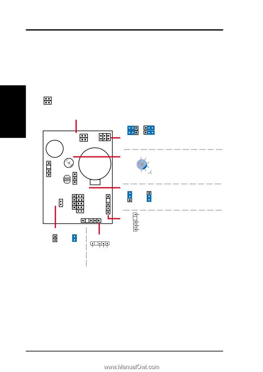
7. APPENDIX ASUS CIDB Module 7. APPENDIX 5. To stop the alarm from sounding, use the BIOS setup or momentarily place a jumper on (or short manually) the CLR jumper. Note that the jumper must be removed for the CIDB to work normally again. 6. If you have an updated BIOS with intrusion support, booting the computer after an intrusion may require a password if configured through BIOS. 7.2.2 Setting up the ASUS CIDB MS1 MS2 MS1/MS2: Micro Switches from the chassis panels can be connected here to trigger chassis intrusion. (Only one pair--MS1 or MS2--should be used for switch open detection.) Buzzer MS1 MS2 SWITCH VR CR2032 3V Lithium Cell OR SWITCH SWITCH 1 1 Close Open SWITCH Close: Intrusion event triggered if either MS1 or MS2 is closed SWITCH Open: Intrusion event triggered if MS1 and MS2 are opened (sensitive) 5 4 VR: 3 Sensitivity adjustment for the photo sensor. 2 (5) is the most sensitive. 0 (not sensitive) 1 (0) is the least sensitive. best range CLR PHOTO PHOTO 1 PHOTO 1 PHOTO: Enable/Disable the Photo Sensor Enable Disable CHASIS CIDBOUT (Reserved) SMBOUT SMBIN CLR CLR Normal Clear Clear: Stops the alarm from sounding SMBCLK Ground SMBDATA +5V SMBIN 1 1 SMBCLK Ground SMBDATA +5V SMBOUT SMBOUT: Connects to another SMB device (if used) SMBIN: Connects to the motherboard's SMB connector through an SMB cable 7.2.3 ASUS CIDB Additional Considerations 1. If there is no power to the motherboard (i.e. removing the power cord or turning the power supply's switch off), the alarm will not sound but the CIDB will still memorize an intrusion event which BIOS will detect on the next bootup. 2. Any chassis intrusion detection components on the motherboard will not work if the CIDB is used. 3. The P2B-LS motherboard must use an external battery pack on the EXTBATT connector or else neither the alarm or intrusion memory functions will work. 98 ASUS CUBX User's Manual
-
 1
1 -
2
-
3
-
4
-
5
-
6
-
7
-
8
-
9
-
10
-
11
-
12
-
13
-
14
-
15
-
16
-
17
-
18
-
19
-
20
-
21
-
22
-
23
-
24
-
25
-
26
-
27
-
28
-
29
-
30
-
31
-
32
-
33
-
34
-
35
-
36
-
37
-
38
-
39
-
40
-
41
-
42
-
43
-
44
-
45
-
46
-
47
-
48
-
49
-
50
-
51
-
52
-
53
-
54
-
55
-
56
-
57
-
58
-
59
-
60
-
61
-
62
-
63
-
64
-
65
-
66
-
67
-
68
-
69
-
70
-
71
-
72
-
73
-
74
-
75
-
76
-
77
-
78
-
79
-
80
-
81
-
82
-
83
-
84
-
85
-
86
-
87
-
88
-
89
-
90
-
91
-
92
-
 93
93 -
 94
94 -
 95
95 -
 96
96 -
 97
97 -
 98
98 -
 99
99 -
 100
100 -
 101
101 -
 102
102 -
 103
103 -
104
-
105
-
106
-
107
-
108
-
109
-
110
-
111
-
112
 |
 |