Asus CUC2000 CUC2000 User Manual - Page 107
ASUS CIDB Intrusion Detection Module
 |
View all Asus CUC2000 manuals
Add to My Manuals
Save this manual to your list of manuals |
Page 107 highlights
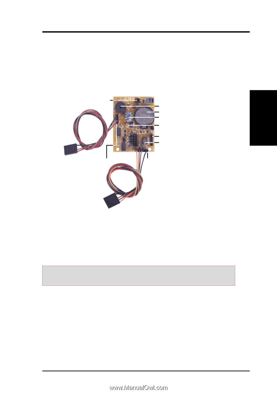
7. APPENDIX ASUS CIDB Module 7. APPENDIX 7.3 ASUS CIDB Intrusion Detection Module The optional ASUS CIDB is a module for providing audible intrusion alarm and logging for ASUS motherboards equipped with the chassis connector. The module detects a chassis intrusion by either light striking its photo sensor or by the closing or opening of a chassis-mounted momentary toggle switch. An intrusion memory function allows detection and clearing the intrusion notification by the BIOS program on the next bootup. Connectors to detect intrusion by chassis mounted micro switches Chassis connector extension cable Buzzer to sound the alarm Battery for the memory Photo sensor sensitivity adjustment Photo sensor to detect intrusion by light Pass-through for another SMBus device Intrusion memory Connector to dock with the motherboard's chassis connector SMB cable Connector to dock with the motherboard's SMBus connector 7.3.1 Using the ASUS CIDB 1. You must have an ASUS motherboard with: (1) a chassis connector and (2) a System Management Bus (SMB) connector. 2. Connect the CIDB directly to the chassis connector or use the provided extension cable and mount the CIDB to the chassis using a double-sided foam adhesive tape or with screws and spacer posts. CAUTION! The CIDB's component pins and metallic points must not come in contact with another metallic surface or else shorting will occur! 3. Use the SMBIN connector and the provided SMB cable to connect the CIDB to the SMB connector on the motherboard. If another SMB device is already used on the motherboard, you may unplug it and connect it to the SMBOUT connector on the CIDB. 4. Check the hardware settings: • PHOTO jumper should be enabled to use the photo sensor. • MS1 and/or MS2 connectors should be connected to momentary toggle switches mounted on the chassis to use the switch close or switch open method for triggering an intrusion event. ASUS CUC2000 User's Manual 107
-
 1
1 -
2
-
3
-
4
-
5
-
6
-
7
-
8
-
9
-
10
-
11
-
12
-
13
-
14
-
15
-
16
-
17
-
18
-
19
-
20
-
21
-
22
-
23
-
24
-
25
-
26
-
27
-
28
-
29
-
30
-
31
-
32
-
33
-
34
-
35
-
36
-
37
-
38
-
39
-
40
-
41
-
42
-
43
-
44
-
45
-
46
-
47
-
48
-
49
-
50
-
51
-
52
-
53
-
54
-
55
-
56
-
57
-
58
-
59
-
60
-
61
-
62
-
63
-
64
-
65
-
66
-
67
-
68
-
69
-
70
-
71
-
72
-
73
-
74
-
75
-
76
-
77
-
78
-
79
-
80
-
81
-
82
-
83
-
84
-
85
-
86
-
87
-
88
-
89
-
90
-
91
-
92
-
93
-
94
-
95
-
96
-
97
-
98
-
99
-
100
-
101
-
 102
102 -
 103
103 -
 104
104 -
 105
105 -
 106
106 -
 107
107 -
 108
108 -
 109
109 -
 110
110 -
 111
111 -
 112
112 -
113
-
114
-
115
-
116
-
117
-
118
-
119
-
120
-
121
-
122
 |
 |