Asus CUEP2-M CUEP2-M User Manual - Page 28
Communication and Networking Riser CNR Slot
 |
View all Asus CUEP2-M manuals
Add to My Manuals
Save this manual to your list of manuals |
Page 28 highlights
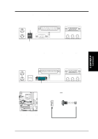
3. HARDWARE SETUP Interrupt Request Table for this Motherboard Interrupt requests are shared as shown by the following table: PCI slot 1 PCI slot 2 PCI slot 3 Onboard VGA Onboard USB controller HC0 Onboard USB controller HC1 AGP Pro CNR LAN CNR Audio/Modem Onboard LAN A B C D E F G H - - - - - not shared - - - - - - - - not shared - shared shared - - - not shared - - - - shared shared - - - - not shared - - - - not shared - - - - - - - - not shared - - - - - IMPORTANT: If using PCI cards on shared slots, make sure that the drivers support "Share IRQ" or that the cards do not need IRQ assignments. Conflicts will arise between the two PCI groups that will make the system unstable or cards inoperable. 3.7.3 Communication and Networking Riser (CNR) Slot This connector supports a specially designed network, audio, or modem riser card. Main processing is done through software and controlled by the motherboard's system chipset. This provides upgradeable network, audio, and/or modem solutions at an incredibly low cost. NOTE: CNRs are not included with this motherboard. 3. H/W SETUP Expansion Cards CUEP2-M ® CUEP2-M Communication & Networking Riser Connectors CNR Restrictions: 1. If an audio CNR card is used, it must be primary. 2. If the onboard audio CODEC is enabled, the modem CNR card must be secondary. 28 ASUS CUEP2-M User's Manual
-
 1
1 -
2
-
3
-
4
-
5
-
6
-
7
-
8
-
9
-
10
-
11
-
12
-
13
-
14
-
15
-
16
-
17
-
18
-
19
-
20
-
21
-
22
-
 23
23 -
 24
24 -
 25
25 -
 26
26 -
 27
27 -
 28
28 -
 29
29 -
 30
30 -
 31
31 -
 32
32 -
 33
33 -
34
-
35
-
36
-
37
-
38
-
39
-
40
-
41
-
42
-
43
-
44
-
45
-
46
-
47
-
48
-
49
-
50
-
51
-
52
-
53
-
54
-
55
-
56
-
57
-
58
-
59
-
60
-
61
-
62
-
63
-
64
-
65
-
66
-
67
-
68
-
69
-
70
-
71
-
72
-
73
-
74
-
75
-
76
-
77
-
78
-
79
-
80
-
81
-
82
-
83
-
84
-
85
-
86
-
87
-
88
-
89
-
90
-
91
-
92
-
93
-
94
-
95
-
96
-
97
-
98
-
99
-
100
-
101
-
102
 |
 |
