Asus CUW-B CUW-B User Manual - Page 38
ASUS CUW-B User's Manual, VGA Header 16-pin VGA, Internal Microphone Connector 3 pin MIC2, True-
 |
View all Asus CUW-B manuals
Add to My Manuals
Save this manual to your list of manuals |
Page 38 highlights
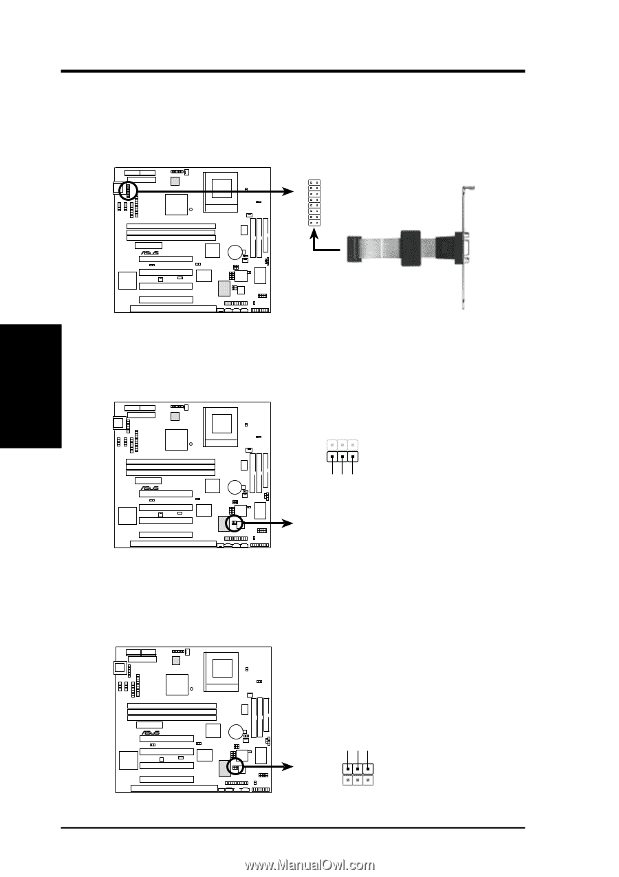
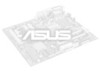
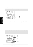
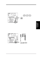
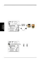
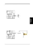
3. HARDWARE SETUP 15) VGA Header (16-pin VGA) The VGA header allows you to connect a standard (CRT) monitor through the provided VGA cable with mounting bracket. Connect the cable to this header and mount the bracket to the case on a free expansion slot. 16 15 Orient the red stripe on the monitor cable with pin 1 21 01 ® CUW-B Bracket to end approximately 6inch CUW-B VGA Header TIP: You may also remove the bracket connector and mount them directly to the case to save expansion slot space. 16) Internal Microphone Connector (3 pin MIC2) This connector allows you to connect a chassis mounted microphone to the motherboard instead of having to attach an external microphone. 3. H/W SETUP Connectors 01 ® CUW-B 1 3 MIC Power MIC Input Ground MIC2 CUW-B Internal Microphone Connector 17) True-Level Line Out Header (3 pin HPHONE) This header allows you to connect a chassis mounted line-out jack for convenient access when connecting to amplified speakers. 01 ® CUW-B HPHONE HP OUT LT GND HP OUT RT 1 3 CUW-B True-Level Line Out Header 38 ASUS CUW-B User's Manual
-
 1
1 -
2
-
3
-
4
-
5
-
6
-
7
-
8
-
9
-
10
-
11
-
12
-
13
-
14
-
15
-
16
-
17
-
18
-
19
-
20
-
21
-
22
-
23
-
24
-
25
-
26
-
27
-
28
-
29
-
30
-
31
-
32
-
 33
33 -
 34
34 -
 35
35 -
 36
36 -
 37
37 -
 38
38 -
 39
39 -
 40
40 -
 41
41 -
 42
42 -
 43
43 -
44
-
45
-
46
-
47
-
48
-
49
-
50
-
51
-
52
-
53
-
54
-
55
-
56
-
57
-
58
-
59
-
60
-
61
-
62
-
63
-
64
-
65
-
66
-
67
-
68
-
69
-
70
-
71
-
72
-
73
-
74
-
75
-
76
-
77
-
78
-
79
-
80
-
81
-
82
-
83
-
84
-
85
-
86
-
87
-
88
-
89
-
90
-
91
-
92
-
93
-
94
-
95
-
96
 |
 |