Asus DAV Center D22 Quick Start Guide - Page 3
Connecting Digital/FM Antenna, Connecting WLAN, Connecting the TV signal source, Connecting
 |
View all Asus DAV Center D22 manuals
Add to My Manuals
Save this manual to your list of manuals |
Page 3 highlights
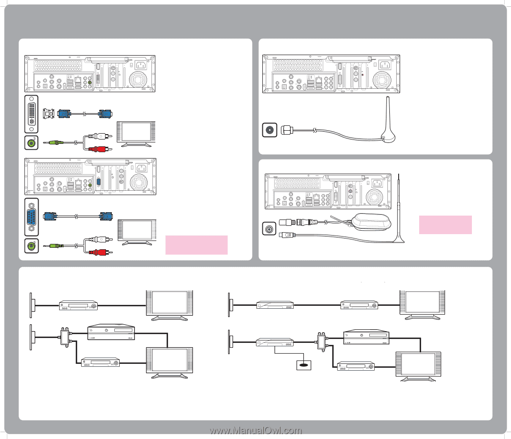
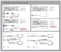
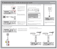
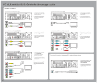
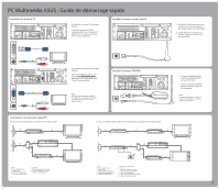
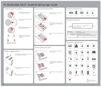
Asus Media Center PC Quick Start Guide Connecting the Monitor 15 VIDEO-IN HDMI TV1 S/PDIF IR 1 IR 2 S/PDIF VIDEO OUT Y Pb s Pr 2.0 2.0 E-SATA CENTER REAR SIDE 2.0 TV2 Connecting to a Monitor Using DVI Out Connect the VGA adapter to the DVI connector on the back of your Media Center PC. Then connect your monitor to the Media Center PC using a VGA cable. Connecting WLAN 15 VIDEO-IN HDMI TV1 S/PDIF IR 1 IR 2 S/PDIF VIDEO OUT Y Pb s Pr 2.0 2.0 E-SATA CENTER REAR SIDE 2.0 TV2 1. Fasten the external antenna provided to the WLAN connector on the back of your Media Center PC. 2. The LED indicator starts flashing indicating the reception of WLAN signals. S/PDIF IR 1 IR 2 S/PDIF VIDEO OUT Y Pb s Pr 2.0 2.0 E-SATA CENTER REAR SIDE 2.0 HDMI 15 TV1 TV2 VIDEO-IN Connecting to a Monitor Using VGA Out Connect the DVI adapter to the VGA connector on the back of your Media Center PC. Then connect your monitor to the Media Center PC using a DVI cable. Note: The cables and connector location are for illustrative purposes only. Connectors may vary by model. Connecting Digital/FM Antenna 15 VIDEO-IN HDMI TV1 S/PDIF IR 1 IR 2 S/PDIF VIDEO OUT Y Pb s Pr 2.0 2.0 E-SATA CENTER REAR SIDE 2.0 TV2 TV1 1. Fasten the NTSC to PAL converter to the digital/FM antenna. 2. Connect the antenna to TV jack on the back of your Media Center PC as shown. Note: The antennas shown here are for illustrative purposes only. Packaged antenna may vary. Connecting the TV signal source Wall to VCR to TV C A B D C E F Wall to cable TV Set-top Box OR Satellite Box to VCR C A B D C E F C G H C A B G C HI H C D RECORDER DVD+R DL C E F Ultra Speed Ultra Speed A B C D E L C I M C JK RECORDER DVD+R DL J C F C G H A Wall B Cable outlet C Coaxial cable D VCR In E VCR Out F TV In G Splitter In H Splitter Out I TV In jack on the back of the Media Center PC A Wall B Cable outlet C Coaxial cable D Set-top box/Satellite In E Set-top box/Satellite Out F VCR In G VCR Out H TV In I Splitter In J Splitter Out K TV In jack on the back of the Media Center PC L Remote control sensor cable M Remote control sensor 3
-
 1
1 -
 2
2 -
 3
3 -
 4
4 -
 5
5 -
 6
6 -
 7
7 -
 8
8 -
 9
9 -
10
-
11
-
12
-
13
-
14
-
15
-
16
-
17
-
18
-
19
-
20
-
21
-
22
-
23
-
24
 |
 |