Asus E500-PI CUSL2-M User Manual - Page 14
Hardware Setup
 |
View all Asus E500-PI manuals
Add to My Manuals
Save this manual to your list of manuals |
Page 14 highlights
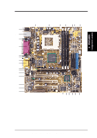
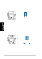
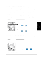
3. HARDWARE SETUP 3.1 CUSL2-M Motherboard Layout PS/2KBMS T: Mouse B: Keyboard USB Top: T: USB1 RJ-45 B: USB2 CPU_FAN DIMM1 (64/72 bit, 168-pin module) DIMM2 (64/72 bit, 168-pin module) DIMM3 (64/72 bit, 168-pin module) FLOPPY SECONDARY IDE PRIMARY IDE DIP Switches COM1 USBPWR1 ATX Power Connector PARALLEL PORT KBPWR Socket 370 DSW PWR_FAN AFPANEL GAME_AUDIO VGA Line Out Line In COM2 LCDTV Super I/O Intel 815E Graphics & Memory Controller Hub (GMCH) IR_CON Mic In AUX ROW 0 1 2 3 4 5 HEADPHONE LED1 Accelerated Graphics Port (AGP Pro) MIC2 CD1 CUSL2-M ® CR2032 3V Lithium Cell CMOS Power MODEM AAPANEL PCI1 Audio Codec AUD_EN1 VIDEO PCI2 LAN_EN WOL_CON 3Com 3C920 Fast Enternet PCI3 CNR1 CHA_FAN Intel I/O Controller Hub (ICH2) CLRTC 4Mbit Firmware Hub (FWH) CNRUSB1 USB2 ASUS ASIC with Hardware Monitor CNRUSB2 JEN ACHA SMB WOR USBPWR2 PANEL IDELED VID Grayed components are optional at the time of purchase. 3. H/W SETUP Motherboard Layout 14 ASUS CUSL2-M User's Manual
-
 1
1 -
2
-
3
-
4
-
5
-
6
-
7
-
8
-
 9
9 -
 10
10 -
 11
11 -
 12
12 -
 13
13 -
 14
14 -
 15
15 -
 16
16 -
 17
17 -
 18
18 -
 19
19 -
20
-
21
-
22
-
23
-
24
-
25
-
26
-
27
-
28
-
29
-
30
-
31
-
32
-
33
-
34
-
35
-
36
-
37
-
38
-
39
-
40
-
41
-
42
-
43
-
44
-
45
-
46
-
47
-
48
-
49
-
50
-
51
-
52
-
53
-
54
-
55
-
56
-
57
-
58
-
59
-
60
-
61
-
62
-
63
-
64
-
65
-
66
-
67
-
68
-
69
-
70
-
71
-
72
-
73
-
74
-
75
-
76
-
77
-
78
-
79
-
80
-
81
-
82
-
83
-
84
-
85
-
86
-
87
-
88
-
89
-
90
-
91
-
92
-
93
-
94
-
95
-
96
-
97
-
98
-
99
-
100
-
101
-
102
-
103
-
104
-
105
-
106
-
107
-
108
-
109
-
110
-
111
-
112
-
113
-
114
-
115
-
116
-
117
-
118
-
119
-
120
-
121
-
122
-
123
-
124
-
125
-
126
-
127
-
128
 |
 |
