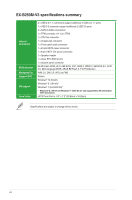
Asus EX-B250M-V3 Users Manual English - Page 11
Clear RTC RAM 2-pin CLRTC, To erase the RTC RAM
 |
View all Asus EX-B250M-V3 manuals
Add to My Manuals
Save this manual to your list of manuals |
Page 11 highlights
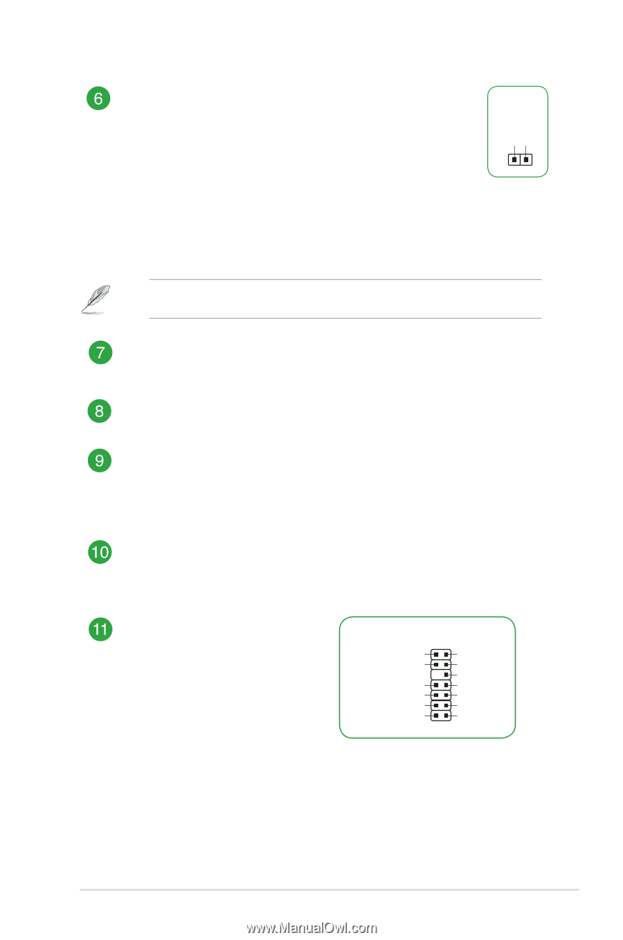
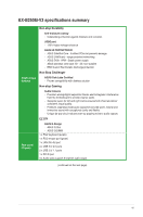
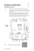
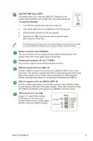
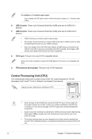
Clear RTC RAM (2-pin CLRTC) This header allows you to clear the CMOS RTC RAM data of the system setup information such as date, time, and system passwords. To erase the RTC RAM: 1. Turn OFF the computer and unplug the power cord. 2. Use a metal object such as a screwdriver to short the two pins. 3. Plug the power cord and turn ON the computer. 4. Hold down the key during the boot process and enter BIOS setup to re-enter data. +3V_BAT GND CLRTC PIN 1 If the steps above do not help, remove the onboard battery and short the two pins again to clear the CMOS RTC RAM data. After clearing the CMOS, reinstall the battery. Speaker connector (4-pin SPEAKER) This 4-pin connector is for the chassis-mounted system warning speaker. The speaker allows you to hear system beeps and warnings. System panel connector (10-1 pin F_PANEL) This connector supports several chassis-mounted functions. USB 3.0 connector (20-1 pin USB3_12) Connect a USB 3.0 module to this connector for additional USB 3.0 front or rear panel ports. This connector complies with USB 3.0 specifications and provide faster data transfer speeds of up to 5 Gbps, faster charging time for USB-chargeable devices, optimized power efficiency, and backward compatibility with USB 2.0. USB 2.0 connectors (10-1 pin USB910, USB1112) Connect a USB module cable to any of these connectors, then install the module to a slot opening at the back of the system chassis. These USB connectors comply with USB 2.0 specifications and supports up to 480Mbps connection speed. TPM connector (14-1 pin TPM) Connect a Trusted Platform Module (TPM) system to this connector to enhance network security, protect digital identities, and ensure platform integrity. TPM +3VSB S_PCIRST#_TBD GND C_PCICLK_TPM +3V +3V F_CLKRUN F_SERIRQ F_FRAME# F_LAD3 F_LAD2 F_LAD1 F_LAD0 PIN 1 ASUS EX-B250M-V3 1-3
-
 1
1 -
2
-
3
-
4
-
5
-
 6
6 -
 7
7 -
 8
8 -
 9
9 -
 10
10 -
 11
11 -
 12
12 -
 13
13 -
 14
14 -
 15
15 -
 16
16 -
17
-
18
-
19
-
20
-
21
-
22
-
23
-
24
-
25
-
26
-
27
-
28
 |
 |