Asus EX-B760M-V7 Users Manual English - Page 17
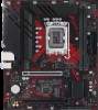
Storage Device Activity LED header +HDD_LED, Power Button/Soft-off Button header PWR_BTN
 |
View all Asus EX-B760M-V7 manuals
Add to My Manuals
Save this manual to your list of manuals |
Page 17 highlights
13. System panel header The System panel header supports several chassis-mounted functions. F_PANEL +PWR_LED- PWR_BTN PWR_LED+ PWR_LEDPWR GND • System power LED header (+PWR_LED-) The 2-pin header allows you to connect the System power LED. The System power LED lights up when the system is connected to a power source, or when you turn on the system power, and blinks PIN 1 when the system is in sleep mode. HDD_LED+ HDD_LED- Ground HWRST# (NC) • Storage Device Activity LED header (+HDD_LED-) The 2-pin header allows you to connect the Storage Device Activity +HDD_LED- RESET LED. The Storage Device Activity LED lights up or blinks when data is read from or written to the storage device or storage device add-on card. • Power Button/Soft-off Button header (PWR_BTN) The 3-1 pin header allows you to connect the system power button. Press the power button to power up the system, or put the system into sleep or soft-off mode (depending on the operating system settings). • Reset button header (RESET) The 2-pin header allows you to connect the chassis-mounted reset button. Press the reset button to reboot the system. Motherboard User Manual 1-5
-
 1
1 -
2
-
3
-
4
-
5
-
6
-
7
-
8
-
9
-
10
-
11
-
 12
12 -
 13
13 -
 14
14 -
 15
15 -
 16
16 -
 17
17 -
 18
18 -
 19
19 -
 20
20 -
 21
21 -
 22
22 -
23
-
24
-
25
-
26
-
27
-
28
-
29
-
30
-
31
-
32
-
33
-
34
-
35
-
36
-
37
-
38
-
39
-
40
-
41
-
42
 |
 |
