Asus H110M-C2 Users Manual English - Page 11
H110 Serial ATA 6.0Gb/s connectors 7-pin SATA6G_1~4, Clear RTC RAM 2-pin CLRTC
 |
View all Asus H110M-C2 manuals
Add to My Manuals
Save this manual to your list of manuals |
Page 11 highlights
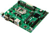
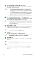
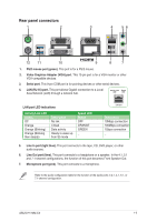
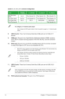
Intel® H110 Serial ATA 6.0Gb/s connectors (7-pin SATA6G_1~4) These connectors connect to Serial ATA 6.0 Gb/s hard disk drives via Serial ATA 6.0 Gb/s signal cables. Chassis intrusion header (4-1 pin CHASSIS) This header is for a chassis-mounted intrusion detection sensor or switch. Connect one end of the chassis intrusion sensor or switch cable to this connector. The chassis intrusion sensor or switch sends a high-level signal to this connector when a chassis component is removed or replaced. The signal is then generated as a chassis intrusion event. By default, the pin labeled "Chassis Signal" and "Ground" are shorted with a jumper cap. Remove the jumper caps only when you intend to use the chassis intrusion detection feature. Clear RTC RAM (2-pin CLRTC) This header allows you to clear the CMOS RTC RAM data of the system setup information such as date, time, and system passwords. To erase the RTC RAM: +3V_BAT GND CLRTC PIN 1 1. Turn OFF the computer and unplug the power cord. 2. Use a metal object such as a screwdriver to short the two pins. 3. Plug the power cord and turn ON the computer. 4. Hold down the key during the boot process and enter BIOS setup to re-enter data. If the steps above do not help, remove the onboard battery and short the two pins again to clear the CMOS RTC RAM data. After clearing the CMOS, reinstall the battery. System panel connector (10-1 pin F_PANEL) This connector supports several chassis-mounted functions. Speaker connector (4-pin SPEAKER) This 4-pin connector is for the chassis-mounted system warning speaker. The speaker allows you to hear system beeps and warnings. USB 2.0 connectors (10-1 pin USB78, USB910) Connect the USB module cable to this connector, then install the module to a slot opening at the back of the system chassis. This USB connector complies with USB 2.0 specifications and supports up to 480Mbps connection speed. TPM connector (14-1 pin TPM) This connector supports a Trusted Platform Module (TPM) system, which can securely store keys, digital certificates, passwords, and data. A TPM system also helps enhance network security, protects digital identities, and ensures platform integrity. ASUS H110M-C2 1-3
-
 1
1 -
2
-
3
-
4
-
5
-
 6
6 -
 7
7 -
 8
8 -
 9
9 -
 10
10 -
 11
11 -
 12
12 -
 13
13 -
 14
14 -
 15
15 -
 16
16 -
17
-
18
-
19
-
20
-
21
-
22
-
23
-
24
-
25
-
26
 |
 |
